Yes a schematic would be great, but many hours of searching and talking to some pinball companies, there just aren’t any to be had. (Since this game is a “home” unit there wasn’t much importance placed on schematics, I’m told)
Here is part of the circuit I can make out, looks like the Zeners are dropping 17V through the 5.6 Ohms Broken resistor then into the 15V Regulator..
Ideally you need to measure the Voltage at the input of the Regulator and at the junction of the Zeners, I would put another regulator in place of the Zener and resistor .
The 1N54001 is being fed from a 28V DC supply from the bridge rectifier, so possibly 39V across the 2200uF capacitor.
If it helps, We seem to have 56vdc coming in.. so it must be loosing up to 26Vdc across the three devices... ( I don't think the reg will stand much more than 30Vdc..
If it helps, We seem to have 56vdc coming in.. so it must be loosing up to 26Vdc across the three devices... ( I don't think the reg will stand much more than 30Vdc..
No it's 28V AC from the Transformer according to the circuit diagram on the manual, making it 28V DC , then smoothing capacitor boosting it to around 39 V..
Yes a schematic would be great, but many hours of searching and talking to some pinball companies, there just aren’t any to be had. (Since this game is a “home” unit there wasn’t much importance placed on schematics, I’m told)
ONCE AGAIN, the regulator really MUST have the bypass capacitors to avoid oscillation. That may be why the circuit failed in the first place. A couple of the cheap 0.1 mfd capacitors right across the regulator terminals. You see them in every application note about power tab regulators. Just because they were not part of the original does not mean that they can be left out. Not every game designer is willing to do things right!
ONCE AGAIN, the regulator really MUST have the bypass capacitors to avoid oscillation. That may be why the circuit failed in the first place. A couple of the cheap 0.1 mfd capacitors right across the regulator terminals. You see them in every application note about power tab regulators. Just because they were not part of the original does not mean that they can be left out. Not every game designer is willing to do things right!
Would you mind detailing that just a bit more? I’m a “tinkerer-jackleg” that has had good luck on some repairs with simple knowledge...some things are a little vague for me and I need a bit more detailed “how to”...
Appreciate yours and everyone’s efforts to help me.
The application notes published by the manufacturer always showed bypass capacitors, those small ones, with a value of 0.1 MFD, connected from both the supply terminal to the common and from the output terminal to the common. On this particular circuit board there is plenty of room to install them on the solder side, using the same pads as the connections to the regulator IC. On this board there are not many of them used. But the ones to use are similar to those small blue blobs about the size of a match head.
Again, my heartiest of thanks to all of you for the help. Unfortunately I’m going to be away from the machine for at least a couple of weeks, but as soon as I get back it will be the first thing on my to-do list. I’ll be sure and let you know my results.
Well, it’s turned out that I’ve been away for a couple months but was able to stop by for a few hours sleep before continuing on...hoping to be back within a couple weeks to try and dig into it further.
However, just for the heck of it, I stuck in a 10ohm, 1/2 watt resistor that I could find in a hurry, powered it up and yep—SMOKED. I figured as much but I only had a few minutes and wanted to try at least a little something. Couldn’t sleep (after driving 15 hours) so I’m back here studying all your comments again, and deciding that yes I have to dig in for tighter views and measurements, to try and get a handle on what’s happening here (the simple mind of mine is saying simply there’s a lot of current coming into that resistor position, and I need to know exacts...I’m sure that would be a great help to all of you too )
More to come soon...at some point in this epic change of life I’m in the middle of—Met love of my life, new state, new home (hers), my old home, all my junk (what in blazes am I going to do with all this stuff?) and trying to figure it all out at 60! I wasn’t ready for this at all!
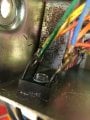
Still can’t sleep and looking at this board (cross-eyed about now)...
Those two diodes to the right of the sink and bad resistor have the label of “IN4733” on them...
Still can’t sleep and looking at this board (cross-eyed about now)...
Those two diodes to the right of the sink and bad resistor have the label of “IN4733” on them...
And it may have already been covered by you guys but...the middle leg of that 7815 runs into a thick trace that runs along he edge of the boardside (looks like a wirewound 1K 7812TRWPW5 10% resistor has a leg tied into it with the other going to the big 2200mf 50V cap, continuing on up to the topside to the second lug of an edge card connector...(I’ve read that these have a couple or so bridge rectifiers up in the main machine box near the power supply that are underperformers and should be replaced...?)
And it may have already been covered by you guys but...the middle leg of that 7815 runs into a thick trace that runs along he edge of the boardside (looks like a wirewound 1K 7812TRWPW5 10% resistor has a leg tied into it with the other going to the big 2200mf 50V cap, continuing on up to the topside to the second lug of an edge card connector...(I’ve read that these have a couple or so bridge rectifiers up in the main machine box near the power supply that are underperformers and should be replaced...?)
The middle leg of a 7815 regulator is the negative terminal, and so the trace it is tied to is the supply negative, probably the common. Looking at the front of the power tab regulator the lead to the left is the supply and the lead to the right is the regulated +15 output.
 Facebook
 Google
 GitHub
 Linkedin