Hey Folks,
Old man here scratchin' his head...
Was involved in analog audio design back in the 70's/80's, but life took me into industrial electronics in the late 80's.
Now retired, I got time to follow up on ideas I had in my youth, but the brain has become fuzzy...
Looking for a simple means to do a linear inversion of an analog DC control voltage...
that is, a variable 0-1.25VDC control voltage with a linear inversion to 1.25-0VDC..
In the u-controller/plc world I was involved in for the last 30 some years, this was a simple task with a couple lines of code.
Of course, all things digital evolved from real world analog of the past...
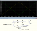
My first thought was a simple voltage divider, from 15VDC to get my 1.25VDC, with a BJT driven from my 0-1.25VDC control voltage.
I get my 1.25VDC with 0VDC to the base of the BJT, and (close to) 0VDC when the base of the BJT is driven 1.25VDC..
But it is not linear in between.. I get about the same result with a FET in place of the BJT..
Of course, this is all simulation in LTSpice...

I keep thinking something like this should be do-able with an op-amp, but my feeble old brain is not clicking...
Any ideas out there??
Old man here scratchin' his head...
Was involved in analog audio design back in the 70's/80's, but life took me into industrial electronics in the late 80's.
Now retired, I got time to follow up on ideas I had in my youth, but the brain has become fuzzy...
Looking for a simple means to do a linear inversion of an analog DC control voltage...
that is, a variable 0-1.25VDC control voltage with a linear inversion to 1.25-0VDC..
In the u-controller/plc world I was involved in for the last 30 some years, this was a simple task with a couple lines of code.
Of course, all things digital evolved from real world analog of the past...
My first thought was a simple voltage divider, from 15VDC to get my 1.25VDC, with a BJT driven from my 0-1.25VDC control voltage.
I get my 1.25VDC with 0VDC to the base of the BJT, and (close to) 0VDC when the base of the BJT is driven 1.25VDC..
But it is not linear in between.. I get about the same result with a FET in place of the BJT..
Of course, this is all simulation in LTSpice...

I keep thinking something like this should be do-able with an op-amp, but my feeble old brain is not clicking...
Any ideas out there??
Last edited by a moderator:


