
Hello everybody,
can somebody tell me how to come up with the equations for this question(in the picture below)?
can somebody tell me how to come up with the equations for this question(in the picture below)?
Attachments
-
 478 KB Views: 26
Not quite, its first year uni electronic & electrical engineering. It's coursework for which none of the lectures have explained what to do.Welcome to AAC!
Is this school work?
If this is something for which you will receive a grade, we consider it homework.Not quite, its first year uni electronic & electrical engineering. It's coursework for which none of the lectures have explained what to do.
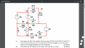
You have all of the voltages and currents already annotated on the drawing. What you need to do is apply Ohm's Law to each resistor in the circuit to come up with equations relating the voltages to the currents.Hello everybody,
can somebody tell me how to come up with the equations for this question(in the picture below)?
Since ohm's law : V=IRYou have all of the voltages and currents already annotated on the drawing. What you need to do is apply Ohm's Law to each resistor in the circuit to come up with equations relating the voltages to the currents.
Remember that Ohm's Law relates the resistance to the voltage across that resistance and the current through that resistance.
Show your best attempt to get as far as you can and we will then have something more to work with to help you move in the right direction.
.png")
Let's focus on R3 for now.Since ohm's law : V=IR
R3=0.5/ I3
What do you think about this?
I don't know how to find the voltage across it. I thought that R3 is connected in series with the other R7,R11,R6 but that does not seem to be the case. Is it V1 maybe?Let's focus on R3 for now.
Where does the 0.5 come from? That should also be "0.5 V" -- units matter!
The question says to write the equations in terms of the labeled currents and voltages. In terms of the node (wire) voltages, what is the voltage across R3 (consistent with I3 being the current through R3)?
What is required for two components to be in series?I don't know how to find the voltage across it. I thought that R3 is connected in series with the other R7,R11,R6 but that does not seem to be the case. Is it V1 maybe?
This is how airliners filled with passengers run out of fuel in midflight and spacecraft get slammed into planets, I've seen someone get killed because they believed as you and just showed units in the final answer.You don't necessarily need units in the equation, only show units in the final answer.
So, I've done this again:What is required for two components to be in series?
The voltage across a resistor is the voltage difference between the two ends of the resistor. The voltage difference between Points A and B is the voltage at A minus the voltage at B. The voltage across a resistor that is consistent with the current through the resistor is the voltage at the end of the resistor that the current enters minus the voltage at the end of the resistor that the current exits.
This is how airliners filled with passengers run out of fuel in midflight and spacecraft get slammed into planets, I've seen someone get killed because they believed as you and just showed units in the final answer.
If potentially getting yourself or someone else killed isn't motivation enough, then I can almost guarantee that if you develop the habit of always properly tracking your units through your work from beginning to end, you will not only see a significant improvement in your grades, but you will also spend considerably less time doing your work overall.
Variables carry their own units. If I haveSo, I've done this again:
R3=(V2-V1)volts/I3 amperes
R6= (V5-2) v / I6 A
R7 = (V2-2) v/I7 A
R9= (V2-V1) v/I9 A
R10= (V4-V3)v / I10 A
R11 =(V1-V5) v/ I11 A
R12= (V4-2) v/ (I10-I7) A
What do you think about this? I added the units this time so planes don't crash.
Remember that both current and voltage are signed quantities (meaning that they have direction associated with them). The voltage used in Ohm's Law is the voltage drop across the resistor in the direction of the current flow, so it is the voltage at the end that the current enters minus the voltage at the end where the current exits. So this should beR3=(V2-V1)volts/I3 amperes
Your volts units distribute so that you have (V5)*(1 V) - (2)*(1 V) giving you something that has units of volts-squared minus something that has units of volts.R6= (V5-2) v / I6 A
What is the voltage on the wire connected to the right end of R7?R7 = (V2-2) v/I7 A
Where is I11 on that diagram?R11 =(V1-V5) v/ I11 A
How do you figure that the current flowing in R12 is different than the current flowing in R10?R12= (V4-2) v/ (I10-I7) A
The wire voltage is not given so, I thought it would be V2 minus the 2v voltage source.What is the voltage on the wire connected to the right end of R7?
I think I made a mistake. The current in R12 is the same as in R10.How do you figure that the current flowing in R12 is different than the current flowing in R10?
The current through R11 would be I6. There is no I11, my mistake.Where is I11 on that diagram?
The 2 V voltage source is establishing that the voltage on the bottom-right wire is 2 V higher than the voltage on the top-right (or middle-right, depending on your viewpoint) wire. It has NOTHING to do with the voltage across the resistor.The wire voltage is not given so, I thought it would be V2 minus the 2v voltage source.
You equation didn't reflect SOME of I7 flowing up into R12, it would only be correct if ALL of I7 flowed upward into R12.I think I made a mistake. The current in R12 is the same as in R10.
I thought some of I7 will flow into that node on the right of R7 and into R12.
By R2 I think you mean R7? Yeah I can see the ground symbol so voltage across R7 will be (0-V2) volts.The 2 V voltage source is establishing that the voltage on the bottom-right wire is 2 V higher than the voltage on the top-right (or middle-right, depending on your viewpoint) wire. It has NOTHING to do with the voltage across the resistor.
But they DO give you the voltage on the wire that is connected to the right end of R2 -- it is indicated by the 'ground' symbol and it means that we are declaring that the voltage on that wire is 0 V and that all other wire voltage will be the voltage difference between the other wire and the ground wire.
Why not I7 = V2/R7 ?Yeah I can see the ground symbol so voltage across R7 will be (0-V2) volts.
You are right.What is the voltage across R9. I legit can't figure that out. I think it might be V1-V2 volts
okay I understandWhy not I7 = V2/R7 ?
You are right.
You are correct -- I meant R7.By R2 I think you mean R7? Yeah I can see the ground symbol so voltage across R7 will be (0-V2) volts.
You are correct -- and notice that this time you got the polarity correct which, coupled with the wrong polarity for R7 would have made getting the correct answers to the problem impossible.What is the voltage across R9. I legit can't figure that out. I think it might be V1-V2 volts but there is also V3 connected.


by Jeff Child

by Jerry Twomey

by Duane Benson

by Duane Benson