Facebook
 Google
 GitHub
 Linkedin
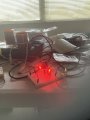
I was toying with these slayer exciter circuits ( I know what you're going to say - internet circuits " lol " ). Anyway long story short I found one that worked but I can't keep the 2N2222 transistor from melting...
2n2222 slayer exciter - Google Search
9 volt battery
22k resistor for the base
LED
2N2222 transistor
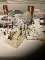
L1 is 2 turns
L2 is 100 turns
everything works the LED lights, the L2 lights a florescent bulb yada yada after 5 mins or so the little 2N2222 starts smoking and then melts. I understand its just a signal transistor and not a power transistor. And its not designed to be a power transistor. My question to whoever comes on board is - what could I do to stop it from melting or getting hot... I don't know enough about electronics to replace it with a TIP3055 or MJE3055T ( which could be connected to a heatsink ). I guess my ultimate goal is to swap to a 3055 but whats the logistics of it.
R
2n2222 slayer exciter - Google Search
9 volt battery
22k resistor for the base
LED
2N2222 transistor
L1 is 2 turns
L2 is 100 turns
everything works the LED lights, the L2 lights a florescent bulb yada yada after 5 mins or so the little 2N2222 starts smoking and then melts. I understand its just a signal transistor and not a power transistor. And its not designed to be a power transistor. My question to whoever comes on board is - what could I do to stop it from melting or getting hot... I don't know enough about electronics to replace it with a TIP3055 or MJE3055T ( which could be connected to a heatsink ). I guess my ultimate goal is to swap to a 3055 but whats the logistics of it.
R