Oh No... Not another Slayer Exciter Question

Audioguru again

Joined Oct 21, 2019
6,673
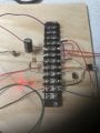
I agree that each long wire is an inductor that barely passes the high frequency. The long wires also have capacitance coupling between them and to ground.
The antique MJE3055 power transistor has low current gain and also works poorly at the high frequency.
 

Audioguru again

Joined Oct 21, 2019
6,673
A TIP31 has a max current rating of 3A and works very well at 0.2A.
An MJE3055T has a max current rating of 10A and also works well at 0.2A.
Both transistors have very poor high frequency response.
Do you know which current and which frequency you need?
 

Thread Starter

RandyFL

Joined Aug 28, 2014
148
I went from 2N2222 ( melted ) to the tip31c. ( the 2N2222 L1 1 - 2 turns 20 awg, TIP31C L1 4 turns 20 awg ) ( L2 s I had commercially made ( 100 turns ). Since the L2 coils were commercially made I didn’t bother with the frequency details or the long wires. I’m looking for 10 - 15 amps 400 volts or higher. ( FJB3307D …? )
I have 2SC3552 s but couldn’t get them to work.
 

Thread Starter

RandyFL

Joined Aug 28, 2014
148
Danko,
What’s the red A on the Q1. I have 5 commercially made coils 100 turns of magnetic wire ( for now I can only adjust L1 with turns … ) I don’t know how many 2N2222 s I have left. Let me study your circuit.
 

Danko

Joined Nov 22, 2017
1,829
What should I replace the MJE3055T with…?
In a market transistor 2SC2078E exists (80V, 3A, 10W, 150MHz, β=200)
US $7.95 / lot (50 pieces).
In common circuit transistor will quickly destroyed, because of about 500V pulses on collector,
but with capacitor C4 collector voltage will not more than 45V.
Circuits parameters w/o C4, with C4:
Current, consumes from V1= 283.5mA, 352.3mA;
Power, dissipates by Q1= 288.3mW, 142.2mW.

1631057184916.png 1631056564688.png 1631074378543.png
 

Attachments

Last edited:

Danko

Joined Nov 22, 2017
1,829
L1 is 2 turns
L2 is 100 turns
The diameter is 1 3/4 inches
The length 2 1/4 inches approximately.
From the EEweb calculator.
Inductance: 0.00130 H
Result from EEweb calculator is invalid.
Use this calculator: https://www.electricaltechnology.org/2014/03/inductance-air-core-inductor-calculator.html
or, better, use Coil32/Coil64 software: https://coil32.net/.
So, for inductance 1,3 mH, coil should contain 405 turns of wire.

Inductance of 100 turns coil is 0.256 mH,
then frequency of generated voltage is 7 MHz.
That explains, why most of 3 MHz transistors
do not work with 100 turns coil at all.

7 MHz, 10 kV circuit:
1631297989776.png1631298309874.png
1631298156094.png1631299228717.png
1631298508113.png1631299547227.png
 

Attachments

Last edited:

Thread Starter

RandyFL

Joined Aug 28, 2014
148
Result from EEweb calculator is invalid.
Use this calculator: https://www.electricaltechnology.org/2014/03/inductance-air-core-inductor-calculator.html
or, better, use Coil32/Coil64 software: https://coil32.net/.
So, for inductance 1,3 mH, coil should contain 405 turns of wire.

Inductance of 100 turns coil is 0.256 mH,
then frequency of generated voltage is 7 MHz.
That explains, why most of 3 MHz transistors
do not work with 100 turns coil at all.

7 MHz, 10 kV circuit:
View attachment 247678View attachment 247680
View attachment 247679View attachment 247684
View attachment 247682View attachment 247685
What are the transistors speeds?
2N2222 ( works but melts )
TIP31C ( works )
2SC3552 doesn’t work
BD243C doesn’t work

the last two don’t work in 100 turns coil.
 

Danko

Joined Nov 22, 2017
1,829
What are the transistors speeds?
2N2222 ( works but melts )
TIP31C ( works )
2SC3552 doesn’t work
BD243C doesn’t work

the last two don’t work in 100 turns coil.
--------------------------------------------------------------------------------------------------------------------------
2N2222 - DATASHEET - https://www.mouser.com/datasheet/2/68/2n2221-1149865.pdf
1631493115765.png

TIP31C - DATASHEET - https://www.mouser.com/datasheet/2/149/fairchild semiconductor_tip31a-549394.pdf
1631492697382.png

2SC3552 - DATASHEET - https://datasheet.octopart.com/2SC3552-Inchange-Semiconductor-datasheet-15978929.pdf
1631493528670.png

BD243C -DATASHEET - https://www.onsemi.com/pdf/datasheet/bd243b-d.pdf
1631493832006.png

2SC2078 - DATASHEET - https://eandc.ru/pdf/import/2sc2078.pdf
1631494066574.png
1631549503766.png
fT
: Gain bandwidth indicates the maximum operating frequency of the transistor.
At this time the collector current ratio with the base current is limited to 1 (hFE=1).
As the frequency of the signal input applied to the base approaches the operating frequency,
the hFE begins to reduce.
When hFE becomes 1, the operating frequency fT is referred to as the gain bandwidth.
fT signifies the operating frequency limit.
However, in actuality for operation the value will be about 1/5th to 1/10th that of fT.
========================================================
https://www.rohm.com/electronics-basics/transistors/understanding-transistors
 
Last edited:

Janis59

Joined Aug 21, 2017
1,834
That Randie`s circuit is extremely popular for aim of Tesla coil empowering, in russia originated sites it have yet another name - kacher Brovina (https://gorchilin.com/articles/scheme/half-wave_kacher_brovin.pdf). The custom components are 2N3055 or russian kT805 (with proper heatsink!!) but NEVER anything tiny-power like 2222. That circuit largest problem is if Tesla coil got a ground to beat through, then base-emitter junktion is flashlikely reverted to smoke cloud. If any shortening of circuit may be expected, then better in this may stand the circuit modification named kacher Gorchilina. Here is link to his original publication https://gorchilin.com/articles/scheme/ or especially the https://gorchilin.com/articles/scheme/kacherP
 
Last edited:

Thread Starter

RandyFL

Joined Aug 28, 2014
148
--------------------------------------------------------------------------------------------------------------------------
2N2222 - DATASHEET - https://www.mouser.com/datasheet/2/68/2n2221-1149865.pdf
View attachment 247821

TIP31C - DATASHEET - https://www.mouser.com/datasheet/2/149/fairchild semiconductor_tip31a-549394.pdf
View attachment 247820

2SC3552 - DATASHEET - https://datasheet.octopart.com/2SC3552-Inchange-Semiconductor-datasheet-15978929.pdf
View attachment 247822

BD243C -DATASHEET - https://www.onsemi.com/pdf/datasheet/bd243b-d.pdf
View attachment 247823

2SC2078 - DATASHEET - https://eandc.ru/pdf/import/2sc2078.pdf
View attachment 247824
View attachment 247866
fT
: Gain bandwidth indicates the maximum operating frequency of the transistor.
At this time the collector current ratio with the base current is limited to 1 (hFE=1).
As the frequency of the signal input applied to the base approaches the operating frequency,
the hFE begins to reduce.
When hFE becomes 1, the operating frequency fT is referred to as the gain bandwidth.
fT signifies the operating frequency limit.
However, in actuality for operation the value will be about 1/5th to 1/10th that of fT.
========================================================
https://www.rohm.com/electronics-basics/transistors/understanding-transistors
Danko,
I have to sit and ponder the " fT " statement...

reading your data...
the BD243C should work in the Tip31C circuit ( I will test the BD243C in the Tip31C circuit this evening )
I built the BD243C circuit and the Tip31C didn't work in it... )
Danko In conclusion ... I built different circuits for this very reason ( for tests )
I haven't given up on the 2SC3552 circuit as I will come back to it with different " Logistics " and if the BD243C and the 2sc2078 circuits can be tweaked to work... I will have the coil(s) made to the parameters with which we both agree on.
 

Thread Starter

RandyFL

Joined Aug 28, 2014
148
That Randie`s circuit is extremely popular for aim of Tesla coil empowering, in russia originated sites it have yet another name - kacher Brovina (https://gorchilin.com/articles/scheme/half-wave_kacher_brovin.pdf). The custom components are 2N3055 or russian kT805 (with proper heatsink!!) but NEVER anything tiny-power like 2222. That circuit largest problem is if Tesla coil got a ground to beat through, then base-emitter junktion is flashlikely reverted to smoke cloud. If any shortening of circuit may be expected, then better in this may stand the circuit modification named kacher Gorchilina. Here is link to his original publication https://gorchilin.com/articles/scheme/ or especially the https://gorchilin.com/articles/scheme/kacherP
Thank you for your input. I haven't counted the 3055 out yet... It is a popular transistor amongst us old dinosaurs. Anyway I think the 2SC3553 is prolly going to be my work horse ( but i would still like to see the 3055 work out ). I will ponder your info and will reflect accordingly.
 

MisterBill2

Joined Jan 23, 2018
18,167
If the 2N2222 transistor gets hot and fails,you need a transistor with the same gain, and at least as high a voltage rating, but a much higher current handling rating. Probably the 2N3055 will not work, both because the gain is not high enough but also because it is not rated for that high a frequency.
 

Thread Starter

RandyFL

Joined Aug 28, 2014
148
Update
After trying various transistors in the circuit using the 2N2222 pattern. I am in agreement with Danko using the 2078 and the 3552 respectively in the configuration that he provided. Also I would use heat sinks on the transistors and fuses in the circuits as things can get hot in research and development. I want to thank Danko for providing the technical help and this forum for providing a place to discuss electronic circuits. I plan to test the limits of each transistor.

R
 
Top