NTC Project (Wheatstone Bridge + Instrumentation Amplifier) - Stuck!

Thread Starter

jonaas18

Joined Apr 4, 2019
67
hi,
You posted these values.

If R1 = R3 and R2 = 2989 (with RT = 182.6), Vcb = - 8.61.

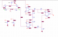
Look at this image, I have marked it up with the voltages.

E
Yes. Im sorry, was having difficulties following. I understood the math. So, that would be my bridge output range. I now have to re calculate my I. A. Right?
 

ericgibbs

Joined Jan 29, 2010
18,766
hi,
No need to be sorry,;)
With such a high Vdiff bridge output, you may have to attenuate the 0V thru 6.3V signal, what actual voltage range do you require.?
E
 

Thread Starter

jonaas18

Joined Apr 4, 2019
67
I gotta end up with 0v - 5v. In order to do so I will have to calculate the gain: AD = vo / vdiff, so.... 5/6.31 = 0.xxx v/V.

I have to design the I. A. According to that gain..
 

ericgibbs

Joined Jan 29, 2010
18,766
hi,
Is it allowed that you use 12V for the bridge excitation voltage, this will give +5.3V max.?
When you are ready, post your new IA design, we can check it out.

Hint: consider the change in Vdiff output if a load resistor is added across the bridge output, say a 5k.??

E
 

Thread Starter

jonaas18

Joined Apr 4, 2019
67
It is allowed. I used 15V just because. I guess it doesn't really matter having 5.3V or 6.3V outside the bridge as I will still have to tone it down i to my voltage range. Nontheless, it may be better to put the voltage down to 12V for enery saving purposes aswell as not having the risk of saturating my op amps.

As for the 5k resistor, I will do my sinulations and find out! I will get back to you in some hours.

Also, should I create a new post about the I. A. In case I run into troubles or should I just post it here?
 

RBR1317

Joined Nov 13, 2010
713
One thing I just noticed is that the "+" and "-" inputs to each op-amp must be at exactly the same voltage. They are not.
Thermister-Bridge.jpg
 

ericgibbs

Joined Jan 29, 2010
18,766
hi,
The original was well out of balance, hence the different voltages.
Look at this sim of that bridge, the values compare with those shown on the original circuit.
E
AA1 05-Apr-19 17.53.gif
 

Thread Starter

jonaas18

Joined Apr 4, 2019
67
I tested the wheatstone bridge with and without the 5k ohms resistance. From what I've noticed, without the 5k resistor and for 12V Vext the bridge works fine. If I then add the 5k resistor to the bridge and change the Vext to 15V, I end up with almost the same thing (either 5.03 or 4.70 accordingly). I'm not sure if that was the intended thing for me to notice :p

I'm also trying to sim my I.A. but I'm running into difficulties with ORCAD Capture. I don't know why but I can't connect any node now. For example, I can't connect a resistance to an opamp. The wire simply stays there without connecting to the nodes (getting of topic but yea ..)
 

Thread Starter

jonaas18

Joined Apr 4, 2019
67
@ericgibbs Ran my simulations. The I.A. is still giving me trouble.

My calculations are nowhere near my simulation results. The bridge Viff is also changing a bit (in the example attatched, it went from beeing 5.31V to 5.30. It's second to none but may not be intended)

I also tried inverting Vdiff (in terms of V+ going to the U1A ampop and V- to the U1B, aswell as V- to U1A and V+ to U1B).
 

Attachments

Thread Starter

jonaas18

Joined Apr 4, 2019
67
Have you consider alternate approaches in place of using a standard bridge circuit?
Kinda. I made some brief research - before starting the project - on wheatstone bridges alternatives and I (think) I found something that explained how I could control my circuit by placing an opamp in Resistance "X" and then having a parallel of resistors on the output (I really don't know the proper terms, was a brief reading).

However, it is required for me to use a wheatstone bridge.

I've designed it properly but I'm still having issues on the output voltage of my I.A. My calcs aren't near my simulation results, and vice versa.

For example, while I calculate a gain 2x for certain resistances, I only get 1.3x on my simulation. I know it is intended to simulate real life situations (since the op amps won't ever be ideal IRL) but still. The difference is way too much that it makes me doubt my circuit.
 

ericgibbs

Joined Jan 29, 2010
18,766
hi jonaas,
The bridge you are using should work OK, confirm that your bridge is configured as per this image.
Also measure the thermistor resistance [ disconnected from the bridge] and post the value and also the ambient temperature of the thermistor.

With the thermistor in the bridge, measure Vdiff and post the value. [ I am assuming the bridge supply is 12Vdc and the thermistor is in the 55C thru 150C temperature range.?]

I suspect you have a problem in your wiring.

E


EDIT:
Are you running your tests at Ambient temperatures.???
At 20C for example the bridge will be well out off balance and the Vdiff will be negative.
Your design range is 55C thru 150C.

Added:
Spanning your thermistor over 0C thru +150C, at 20C Tamb gives -3.73V !
Ref 2nd image.
 

Attachments

Last edited:

Thread Starter

jonaas18

Joined Apr 4, 2019
67
hi jonaas,
The bridge you are using should work OK, confirm that your bridge is configured as per this image.
Also measure the thermistor resistance [ disconnected from the bridge] and post the value and also the ambient temperature of the thermistor.

With the thermistor in the bridge, measure Vdiff and post the value. [ I am assuming the bridge supply is 12Vdc and the thermistor is in the 55C thru 150C temperature range.?]

I suspect you have a problem in your wiring.

E


EDIT:
Are you running your tests at Ambient temperatures.???
At 20C for example the bridge will be well out off balance and the Vdiff will be negative.
Your design range is 55C thru 150C.

Added:
Spanning your thermistor over 0C thru +150C, at 20C Tamb gives -3.73V !
Ref 2nd image.
Starting out, the bridge is completly the same as the one you made. If I run the simulation with it alone, I get the Vdiff = 0V when RT is 2989 (balanced bridge) and Vdiff = 5.31 when RT=182.6.

I don't know what do you mean by measuring the thermistor resistance. It's resistance at ambient temperature (we have always used 25°C) is 10k ohm.

I didn't change my simulation temperature, so, by default, it is running at ambient temperature for sure. However, only the resistances are at ambient temperature as I am manually changing my RT value to either 2989 (sensor's resistance at 55C) OR 182.6 (sensor's resistance at 150C). Do you understand? Am I doing this wrong? I thought I was supposed to do this. (even though I have noticed that I have my sensor model in orcad).

With this said, I can hit the values I pre calculated (0v or 5.31) for the temperature limits, no idea about the in between values (i.g. for 90C, 120C, etc....). Vext is 12V, yes.

Perhaps my problem is i am using a resistor simulating my sensor and not the real sensor. I am also making transient simulations (time), as I dont know which other to choose, DC sweep, etcetc. There is one simulation profile to simulate V = f(T(°C)) and I can change the parameters to [55 to 150] °C, but if I do this, the whole circurt will be at i.g. 100°C ... While in real life, I am only going to heat up the sensor and keep everything at 25-30°C
 

ericgibbs

Joined Jan 29, 2010
18,766
hi j,
My 2nd image [above] shows 10k for the Thermistor at 25C, I extended the curve down to a lower temperature in order to show what Th resistance value you should expect at 25C.

Is the resistor you are using as a thermistor equivalent, a variable resistor, say in the order of 2.5K and a 180R in series , if yes then that should be OK to test the bridge range Vdiff out.

I will draw your complete circuit in LTSpice and run a simulation, it may highlight a problem in your IA design.

In theory the circuit should work fine, it is a typical Bridge & IA set up.

E
 

Thread Starter

jonaas18

Joined Apr 4, 2019
67
hi j,
My 2nd image [above] shows 10k for the Thermistor at 25C, I extended the curve down to a lower temperature in order to show what Th resistance value you should expect at 25C.

Is the resistor you are using as a thermistor equivalent, a variable resistor, say in the order of 2.5K and a 180R in series , if yes then that should be OK to test the bridge range Vdiff out.

I will draw your complete circuit in LTSpice and run a simulation, it may highlight a problem in your IA design.

In theory the circuit should work fine, it is a typical Bridge & IA set up.

E
As far as for the curve, I understand the 10k at 25C "thing". I myself had to manually input the values on a Excel list and find out the graph + Its exponencial equation for my paper. The resistor isn't an equivalent, it is simply a R/Analog resistance (just like the other ones). Should I swap it for my sensor model and try to define temperature values for it?

I am sorry for beeing newbie at this. I understand the theorical part but I am still very new on circuit designing and finding out what is wrong.
 

ericgibbs

Joined Jan 29, 2010
18,766
hi,
I am currently drawing out your circuit, will post when tested.
I guess you know that the resistance response of a Thermistor is exp' versus temperature.
There are methods for adding resistors in an attempt linearise the resistance, but these are only much good over short temperature spans.
Some users connect the Vout of a IA into the ADC input of a micro-controller and linearise the readings in the program.

A thermistor would not be my choice for 55C thru 150C, a small device like a LM35 IC, which gives linear Vout would be my choice.

E
 
Top