NPN understanding base emitter voltage

Thread Starter

digitsboy

Joined Dec 29, 2016
48
Hi,

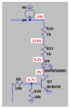
i try to understand the following circuit. Especcially transistors circuits. I have a question.
When the output of comeprator U1 is high. the base voltage of transistor Q1 is also getting high, which leads that V4 can flow to ground via Q1.
I had a discussion with a friend about this circuit and he said that the VCE can't be 10mV. That in saturation mode de VCE must be higher. When i look in the datasheet it is saying that the VCE(sat) is typical 90mV and maximum 200mV. So why is the LTSPICE value 10mV? I used the official spice model?

hopefully someone can clear this up for me
thanks in advance!
trans.PNG
 

Attachments

Papabravo

Joined Feb 24, 2006
21,225
Look at R7. It has a value of 22K Ω. That means the collector current from V4 will be on the order of 11 mA. Is it possible that Vce might be affected by the actual collector current? Is it possible that at higher collector currents the value of Vcd(sat) might be higher? The writing on your schematic is too small to read so I can't tell what type of transistor you are working with.

I am curious about why exactly there are six identical, but separate power supplies of 24 Volts. AFAIK, nobody designs circuits like that.
 

Bordodynov

Joined May 20, 2015
3,180
The saturation voltage depends on the ratio of vase and collector current. The higher the base current, the lower the saturation voltage. But there is a minimum. Very high currents increase the saturation voltage.2019-11-01_08-50-18.png
 

crutschow

Joined Mar 14, 2008
34,452
Look at R7. It has a value of 22K Ω. That means the collector current from V4 will be on the order of 11 mA.
I think you mean 1.1mA. :)

When i look in the datasheet it is saying that the VCE(sat) is typical 90mV and maximum 200mV. So why is the LTSPICE value 10mV? I used the official spice model?
But not under the same conditions as in the data sheet.

The data sheet Vce(sat) graph shows a voltage of about 40mV for a 1mA collector current, with a base current 1/20th of the collector current or 50uA (below).
1572590520589.png
Your simulation is using a base current of about 777uA which is over ten times the data sheet value, and that accounts for the low saturation voltage.

Below is the simulation for 1mA and 50uA base current, which gives a saturation voltage of 40mV, the same as the data sheet graph.

Moral: Read all the info in the data sheet, don't cherry pick. ;-)

1572590268252.png
 

Audioguru again

Joined Oct 21, 2019
6,692
The text is very hard to read because the parts are extremely far apart. the enormous distance between the parts is because the accuracy of the voltages is so long. 721.7871mV is 0.7V isn't it?

The schematic should have parts closer together like this:
 

Attachments

Audioguru again

Joined Oct 21, 2019
6,692
Why do you simulate such a simple circuit? It is easy to calculate the voltages.
It is simple to design, for a transistor to turn on then its base current should be 1/10th to 1/20th its collector current.
Why use a 24V supply to light one LED on each side? The circuit will work fine with a 12V supply since its input voltages are almost 8V.
R8 and R10 do nothing and should be removed.
 

Audioguru again

Joined Oct 21, 2019
6,692
You design by "trial and error"?
I design using minimum and maximum datasheet spec's and proper theory so that my circuits always work perfectly even if the parts have minimum or maximum spec's.

Simulations use "typical" spec's so some of the circuits malfunction unless you test and select spec's for each part.
A sim program usually does not even know that a little 0.625W transistor catches on fire or explodes when overloaded with 3W.
 
Top