Facebook
 Google
 GitHub
 Linkedin
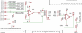
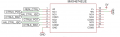
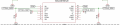
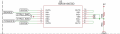
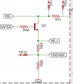
Hi, I have built the attached circuit. It is meant to control the power consumed by the bulb. The power feedback in the illustration is just a difference multiplied by a gain and the voltage across the bulb. However in the real circuit the power is measured by the MAX4211DEUE power monitor. For low base currents, the transistor will open up and allow current to flow through the light bulb as predicted. However if I saturate the transistor fully and wait a little while, I'll find that I can't pull it out of saturation even if I bring the opamp setpoint low. The bulb resistance in the figure is slightly misleading because it changes with the temperature of the bulb. However, the opamp model is correct, and the transistor part number is correct.
Can I get some advice to figure out what is going on? The current through the bulb when this happens is about 0.5 amps. Is the Vce getting too low and creating some kind of equilibrium that makes the control loop not work? My initial thought to solve this problem is to not let the current through the bulb get so high, but does anyone have any other suggestions?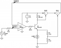
Can I get some advice to figure out what is going on? The current through the bulb when this happens is about 0.5 amps. Is the Vce getting too low and creating some kind of equilibrium that makes the control loop not work? My initial thought to solve this problem is to not let the current through the bulb get so high, but does anyone have any other suggestions?