Noob Trying to Make a a power box for my trolling motor

Thread Starter

Dane_West

Joined May 31, 2024
12
Thanks MisterBill. I did think about that. I wasn't sure so I thought putting the relay in would completely disconnect it when the switch is in the other on position. My thought process was a concern with power from the battery going backwards into the charger and transforming it 120V on the plug.

And yes, I plan on using some inline blade fuses to protect the relays, meter and charger.

Thanks Again!
 

MisterBill2

Joined Jan 23, 2018
28,113
Thanks MisterBill. I did think about that. I wasn't sure so I thought putting the relay in would completely disconnect it when the switch is in the other on position. My thought process was a concern with power from the battery going backwards into the charger and transforming it 120V on the plug.

And yes, I plan on using some inline blade fuses to protect the relays, meter and charger.

Thanks Again!
Power going backward thru a device is certainly done on rare occasions, but it requires a lot of very intentional design effort and quite a few extra components. So it would not happen with your charger. The charger converts incoming mains AC power into DC power at some controlled voltage and current. The circuit to reverse that function would have no application value in the case of a simple battery charger. A separate issue, which I may not have been clear enough about, would be that the charger might possibly not allow battery power from leaking back from the battery to the charger. BUT that check is described in post #20, and only requires that you have a multimeter that can measure current. A digital multimeter is the preferred tool to do the check. THEN you will know..
What might have created the confusion is that TRANSFORMERS DO work in both directions, in fact they do it quite well. And, then, in the charger there may well be a transformer, providing both the desired voltage change and also providing isolation from the mains power. The difference is provided by what follows the transformer, which would be DIODES. They serve the purpose of converting the AC power to direct current, by allowing current (charge) to pass in only one direction. Those diodes ALSO prevent power from flowing back into the transformer. That is a ONE WAY arrangement, and so reverse power flow is prevented.
 
Last edited:

MrAl

Joined Jun 17, 2014
13,777
Thanks MisterBill. I did think about that. I wasn't sure so I thought putting the relay in would completely disconnect it when the switch is in the other on position. My thought process was a concern with power from the battery going backwards into the charger and transforming it 120V on the plug.

And yes, I plan on using some inline blade fuses to protect the relays, meter and charger.

Thanks Again!
Hi,

There is almost no way power would get reversed all the way back to the 120vac plug, but with many chargers if the power is lost for any reason (120vac line down) the battery will be drained by the charger. That's a very typical problem and has to be thought about with any charger design. Sometimes the drain is very small so it would take some time to drain the battery, but over time it could drain it a lot of the 120vac line goes down for some longer time, or it becomes unplugged.
So this is a very legitimate concern.

Another option is to have the power line itself power one of the relays so if the 120vac power gets turned off or unplugged, the charger is disconnected from the battery completely.
If the motor will never, ever, be run with the charger being used to charge the battery at the same time, you may only need one relay then.
 

Thread Starter

Dane_West

Joined May 31, 2024
12
I was thinking that too. My only concern was the amperage going through the switch. The specs on the charger say " Rated Charge Current: 20A " which I think means that 20A will be going directly through the switch to get to the battery. Is that a bad idea?
 

MrAl

Joined Jun 17, 2014
13,777
I was thinking that too. My only concern was the amperage going through the switch. The specs on the charger say " Rated Charge Current: 20A " which I think means that 20A will be going directly through the switch to get to the battery. Is that a bad idea?
No the current goes through the relay contacts. I don't think you need a switch then because it switches when it is plugged in. If you still want an on/off switch, just have the switch also control the relay coil. If you need two relays, that's almost the same.
 

MisterBill2

Joined Jan 23, 2018
28,113
No the current goes through the relay contacts. I don't think you need a switch then because it switches when it is plugged in. If you still want an on/off switch, just have the switch also control the relay coil. If you need two relays, that's almost the same.
The charging current IS a valid concern, that had slipped past me. A 20 amp switch, even for lower voltage DC, will not be cheap or small. A single pole 12 volt powered relay to break one side of the battery charge connection will be adequate, but it will require a switch to use it. If the battery really is only 12 volts then no series resistor will be required. Be sure to take the 12 volt power for the relay from the charger side, to avoid not being able to charge a totally dead battery.
 

Thread Starter

Dane_West

Joined May 31, 2024
12
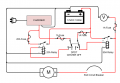
This has been awesome. Thanks for all the input. I think I got it now. Mr. Bill brought up a good point. If the battery doesn't have enough juice, it won't power the relay for the charger. Putting that relay on the positive side of the charger I think will require a DPDT Center Off switch because I now have different power input.

I've updated the drawing. I changed drawing program. My trial expired. This is DigiKey's free one. I also added inline fuses where I think I need them. Check it out and let me know any thoughts.

Thanks again!
Dane
 

Attachments

MisterBill2

Joined Jan 23, 2018
28,113
You really do not need to use a relay to disconnect the trolling motor. I doubt that it would be switched on while you are charging the battery. It might even be disconnected if you move the battery box to charge. That 50 amp relay will draw a fair amount of current just to stay energized, wasting battery power.
 

Thread Starter

Dane_West

Joined May 31, 2024
12
I got you. A couple of different scenarios popped into my head. Just to clarify. I can't run 50A through the switch. I could just connect the trolling motor directly to the battery via the circuit breaker. The trolling motor does have its own controls (looks to be a 5 position switch). I guess I could also connect the charger directly to the battery. As long I don't try to charge the battery and run the motor at the same time which would never happen. And since we are fairly sure that keeping the charger connected to the battery won't pull power from the battery, means I really don't need any of this. All I really need are some marine style power connectors and the volt meter. Right?
 

MisterBill2

Joined Jan 23, 2018
28,113
If you have a meter capable of measuring current then it will be simple to verify that there is no leakage current flowing into the charger from the battery when the charger is not powered. Otherwise, for a quick check, connecting a small 12 volt light in series with the charging connector can also reveal if there is leakage. If the light in series does not light at all, or even glow a bit, then there is not any significant current flowing. That indicates that it will not cause a problem for the charger to remain connected to the battery when not charging. That makes the connection scheme simpler and probably easier.
 

MisterBill2

Joined Jan 23, 2018
28,113
In this case the fun would be in using the package rather than creating it. BUT there would still be the installation of the battery voltage meter and the momentary switch to allow checking the battery voltage. The fun would be the electric drive ride home at the close of the day. You might even decide to power a music machine to add some foreground sound, now that you have 12 volt power on board.
 
Top