Noninverting opamp AC performance

Thread Starter

Pyrex

Joined Feb 16, 2022
552
Hi,
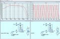
I want to buid a noninverting opamp for my cable tracer . The opamp will be powered from batteries , +4V and -4V , frequency range is from 30Hz to 4kHz, gain is 250, 1mV at the input. I found a dozen LM308 op-amps in my box and a few LT1012s and did an LTSpice simulation.
The simulation showed fairly modest results at AC , even though the frequency wasn't high.
At 500Hz the gain was about 250, just as expected.
At 2kHz the gain was about 225.
At 4kHz the gain dropped to 170. Not good.
Similar results were also seen with the LT1012 opamp.

What would be the solution? Use completely different opamps, much faster ones?
Somehow I never thought that for such a relatively low frequency, fast op-amps would be needed
 

LvW

Joined Jun 13, 2013
2,037
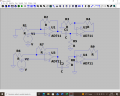
Any question concerning an electronic circuit (and its performance) requires a corresponding circuit diagram.
Otherwise, a good and helpful answer cannot be given.
 
When looking at op-amps there are two things to watch at high frequencies.
Slew Rate, which is 50V/uS in this case.
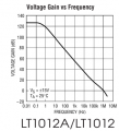
Unity gain bandwidth. Which I think is 2mhz for this part. The only bandwidth number on this data sheet is Open Loop Bandwidth. If 2mhz is the limit, then at 1mhz you can only get a gain of 2 max. At 100khz =gain of 20x. At 10khz =gain of 200x max. The graph on post #5 makes me think the 2mhz number is about right.
1790431533124.png
---------edited----------------
For the other op-amp:
Here is its max gain verses frequency. You can see that at 1mhz it has no gain. (gain=1x)
1790432776927.png
Here is how fast the output can move. 0.2V in one uS is very slow.
1790432885832.png
 
Last edited:

crutschow

Joined Mar 14, 2008
38,819
Edit: Added two op amp simulation-

So the op amp gain-bandwidth product is too low for a single op amp with that gain.

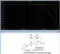
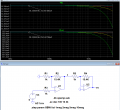
The LTspice top sim below shows the circuit gain with a generic op amp model gain-bandwidths of 1MHz (green), 2MHz, 5MHz, and 10MHz (blue):
Note that even a 10MHz GBW gives a slight rolloff at 4kHz.

But if you use two op amps in series, each with the square root of the desired total gain (16), then a 1MHz GBW is sufficient (bottom sim):
The -3dB bandwidth of that pair is about 40kHz.
Edit 2: The apparent increase in the -3dB gain-bandwidth for two identical gain op amps in series equals the gain of the one amp times approximately 65% of the gain-bandwidth of the op amp.
Thus for a gain of 16 for each amp with the nominal jelly-bean op amp gain-bandwidth of 1MHz, the output apparent gain-bandwidth of the two in series will be 16 * 0.65 * 1MHz = 10.4MHz, giving an output -3dB frequency of 10.4MHz / 256 = 40.6KHz.


1790439694057.png

1790441159488.png
 
Last edited:

Thread Starter

Pyrex

Joined Feb 16, 2022
552
It's pity. So, I see, not LM308 , nor LT1012 are not suitable for the task.
And, in addition, the output is significally shifted from GND. And that's not good, because if there was a strong pulse at the input, the output would be clipped, and that would cause extra noise.

It seems to me, it is better to use two opamps in series ,decoupled with a capacitor, first of them may be a noninverting, and second- an inverting opamp. The phase sign at the output on my device doesn't matter. I would consider using two LM308, and the gain of each would be 16 only
 

Thread Starter

Pyrex

Joined Feb 16, 2022
552
Okay, I see how you are saving a resistor.
So if you use the identical resistor values of 1kΩ and 15.4kΩ for both the inverting and non-inverting amps, the total gain will be about 252.5 (below):

View attachment 371725
Sorry, but I didn't really understand why you're not putting a capacitor between the opamps? Such a capacitor will cancel out the first op-amp's bias voltage effect.

And one more question. Should I use RC circuits for Vcc and Vee for each opamp? This question came up because of the relatively high gain.
 

crutschow

Joined Mar 14, 2008
38,819
I didn't really understand why you're not putting a capacitor between the opamps?
I didn't put it in because it would have no affect on my AC simulation, but the real circuit should have the capacitor.
If you want no output DC offset you could also add a capacitor there (perhaps then the one between the op amps wouldn't be needed).
Should I use RC circuits for Vcc and Vee for each opamp?
Yes, you should decouple Vcc and Vee on all op amp packages with a 100nF capacitor (no R needed).
Again, I didn't show them since the simulator uses perfect Vcc and Vee sources and thus would have no effect on the simulation.
 
Last edited:

crutschow

Joined Mar 14, 2008
38,819
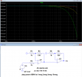
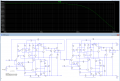
Below is the AC sim of two of your LM308 transistor-level model amps in series with a 1mV input, the left non-inverting and the right inverting:
I changed the gain resistors to 10kΩ and 154kΩ to reduce the output load for the left op amp, giving a non-inverting gain of 16.4 and an inverting gain of 15.4 for a combined gain of 252.
(Again I left out any coupling or decoupling capacitors.)

The gain is less than 0.1dB down at 4kHz with the -3dB point at 30kHz, for a equivalent gain-bandwidth of about 7.5MHz at that gain.

1790617756899.png
 

Attachments

Last edited:
Top