Noninverting Power Amplifier for Function Generator

Thread Starter

TCwarrior24

Joined Jan 3, 2019
11
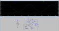
I am trying to build a noninverting variable power amplifier for a function generator. The power amplifier will take an input voltage and current of +/-5 Vpp and +/-0.250 A at 1kHz signal signal from the function generator and amplify the signal to +/-10 Vpp and +/-5.0 A to a higher resistance loads (between 1-100 Ohms).

I am using:
  1. (1) APEX MP108 Power Operational Amplifier. (https://www.apexanalog.com/products/mp108.html)
  2. (2) MEAN WELL AC/DC CONVERTER 24V 200W (https://www.digikey.com/en/products...?s=N4IgTCBcDaIIwA4BsSC0BRASgBVWADPngCwgC6AvkA)

1726004272509.png

I have somewhat of a design on LTSpice that works but going forward, I do have a lot of questions and concerns:
- I am using a current limited resistor (Rcl) to cap at 5 amps but I am not getting nowhere near 5 amps.
- When I change my SINE(0 1 100) to something higher then 1 V, it starts to turn into a trapezoid waveform.
- I am using for ohms to test for a 5 amp output current, but when setting up for higher load resistance, how would I prepare this design for that?
- For the variable part of the amplifier, would I need to add another resistor in parallel and make that the variable resistor? I did see a design on this but I was wondering the amplifier will not be able to fully achieve unity gain or the full gain output.
-Does this design need to be biased? I do have somewhat of an understand this but do know if when or if it "SHOULD" be utilized.
-I do want to include a variable DC offset (but that can come later)
-I am not to entirely too sure about the gain because when I do the calculations for 1 input, it will change when I redo the calculations for another with a different input voltage. So I am not to sure if there is a way that I can put a cap on the output voltage of 10 V.
-In the datasheet, it says this about the Voltage Swing, I am trying to figure out what it means.
1725983076446.png
-Am I missing anything else that I should or need or recommendations of incorporating?

This will be one of first designs using opamps and I am getting "lost in the sauce" when I start reading about opamps I tent to start going to other topics like current limiting, biasing, buffers etc. I also want to try to learn about this as much as I can and do the work and understand it for my own.
 

Attachments

Alec_t

Joined Sep 17, 2013
15,103
My reading of the datasheet is that at 10A output current the output voltage can't reach within as much as 10V from the power rails. That implies an output impedance of about 1 Ohm and likely accounts for the trapezium waveform.
Any introduced DC input bias from ground should result in a DC offset at the output, if you need it.
 

LowQCab

Joined Nov 6, 2012
5,101
Your performance requirements are absolutely brutal.
You may not fully understand what it is that You are asking for.

Please start-out by fully defining the performance that You require, and under what conditions,
( and for the rest of us ),
exactly why You require those extreme levels of performance.

What You want so far will require a large fan-cooled Heat-Sink,
and careful attention to mounting,
or You will run the risk of smoking your very expensive Module.
.
.
.
 

BobTPH

Joined Jun 5, 2013
11,463
How do you expect to get 5A through a 4Ω resistor with a voltage of 11V?

You simulation shows approximately 11V and 2.75A, which is correct. To get 5A you would need an output of 20V.
 

sparky 1

Joined Nov 3, 2018
1,218
Test the op amp offset. That is, connect both inverting and non inverting inputs to ground. Try to achieve zero.
An offset adjustment is then made so that with both inputs grounded the output, using a fine adjustment is Zero. Now inputs match.
Why?, because the offset error will be amplified. After your gain (amplitude) is set correctly then review the current.
Plenty of goofy things happen when you attempt the next stage with poor offset adjustment.
We leave a test point with noted voltage in case there is change in op amp parameters circuit adjustments can be performed by
a qualified magician.
How to Buffer an Op-Amp Output for Higher Current, Part 1 - Technical Articles (allaboutcircuits.com)
 
Last edited:

Thread Starter

TCwarrior24

Joined Jan 3, 2019
11
My reading of the datasheet is that at 10A output current the output voltage can't reach within as much as 10V from the power rails. That implies an output impedance of about 1 Ohm and likely accounts for the trapezium waveform.
Any introduced DC input bias from ground should result in a DC offset at the output, if you need it.
I am trying to design a cheaper version of this (these are priced at 3,000):
https://accelinstruments.com/Products/TS200/TS200-Description.html
 

Thread Starter

TCwarrior24

Joined Jan 3, 2019
11
Your performance requirements are absolutely brutal.
You may not fully understand what it is that You are asking for.

Please start-out by fully defining the performance that You require, and under what conditions,
( and for the rest of us ),
exactly why You require those extreme levels of performance.

What You want so far will require a large fan-cooled Heat-Sink,
and careful attention to mounting,
or You will run the risk of smoking your very expensive Module.
.
.
.
I am trying to design a cheaper version of this:
https://accelinstruments.com/Products/TS200/TS200-Description.html

These cost about $3,000 and I know I can make one for about $200-$500 and all I am interested in is increase the output current.
 

Thread Starter

TCwarrior24

Joined Jan 3, 2019
11
How do you expect to get 5A through a 4Ω resistor with a voltage of 11V?

You simulation shows approximately 11V and 2.75A, which is correct. To get 5A you would need an output of 20V.
That's where I am getting confused. I am supplying +/-24V to the rails, in my mind, I am thinking the output voltage should cap out around +/-24V. but is stopping around 15V. Is that where the output swing equation come into play?


I am trying to design a cheaper version of this:
https://accelinstruments.com/Products/TS200/TS200-Description.html

These cost about $3,000 and I know I can make one for about $200-$500 and all I am interested in is increase the output current.
 

MisterBill2

Joined Jan 23, 2018
27,167
That description would also define an externally programmable power supply with very fast response time, tied to a function generator. The fastest power supply slew-rate will define the frequency response, exactly the same as for the externally programmable supplies. So now there is another area to look into for designs. If you intend to copy the circuit of a "direct coupled " audio amplifier you will need a much larger heat removal system for the power transistors. And probably an amplifier with twice the power rating as the power supply would have, because the current will be constant, not peaks.

One possible less costly choice would be to find a adequate power supply capable of remote sensing, that had adequate response times. The whole project depends on a lot more than just the voltage and the current requirements for your application.
And like many others, the TS has already shown us their selected solution. And asked for help now that it does not work. Simply boosting the power of a waveform simply takes an appropriate amplifier.

It seems now that I recall providing a workable scheme to achieve the same results in another thread just a few weeks ago. That solution would certainly work for this application, although producing an accurate square wave would be a problem.
 

atferrari

Joined Jan 6, 2004
5,001
You repeat, repeat and repeat the same text with minor variations. Why? Is that the way you do when maintaining a conversation? Wow!!
 

MisterBill2

Joined Jan 23, 2018
27,167
Exactly the same format as another recent thread. And the TS claims, in "Information" to be an electrical engineer. That means having gone thru, at least, basic electricity courses 1 and 2, and basic electronics 1 thru 4. OP-amps are covered in course #3
The device linked to in posts 8,9, 10, and 12 is a piece of test equipment.
So now I have a very specific question, with quite a bit depending on the answer given: What sort of test is planned using this power boosted DC supply plus signal generator setup???

The statement of capability : " and amplify the signal to +/-10 Vpp and +/-5.0 Amps." That could be as simple as a 50 watt HIFI amplifier, except for the signal being a square wave. That link also describes quite a few potential applications, but not all of then require the high power with the DC bias. The most obvious would be to verify the "power supply rejection ratio" of some electrical assembly.
So I am not asking for product information, but rather a description of the test, or other use, of the desired system.
 
Last edited:
Top