 Facebook
 Google
 GitHub
 Linkedin
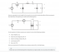
Hello, I am having trouble with getting the proper expressions. I have an nonideal buck converter (attached) Based on the model and expressions provided, I came up with Re = D^2*RL or RL (neither is correct), Ve = D*VF or VF (neither is correct), M = D (correct), V= D*(Vg-VF)*(R/(R+D^2*(RL))) (not correct), and without getting the other answers correct i really can't solve for the efficiency in #8.
Could someone explain where I am going wrong?
Could someone explain where I am going wrong?
Attachments
-
 194.7 KB Views: 15
 -
 131.1 KB Views: 14
 -
 110.2 KB Views: 9


