Noise Reduction in Amplifier Circuit

Thread Starter

ignite

Joined Jan 31, 2008
18
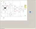
Hi I have designed a differential amplifier circuit to act as a kind of a weighing scales, the Wheatstone bridge consists of 2 very sensitive strain gauges, since im amplifying such a small voltage my gain is required to be about 8,000 to get a reasonable measure. But as you are aware this causes problems for any noise present in the circuit as it will just swamp my signal and I wont get any readout, cud I have advice about the possibility of placing smoothing capacitors (size,type,location) and the possibility of using filters. I’ve included a schematic of my circuit model.

Thanks
 

Attachments

scubasteve_911

Joined Dec 27, 2007
1,203
Hi,

Your circuit can be optimized for noise reduction in a couple of ways. First of all, you can introduce a first order pole to your buffer amplifiers. This is only if you know the dynamics of your system are in a position to know what your cutoff frequency should be. Since noise is ideally 'white', then having the pole besides your opamps GBW will cut down the noise power into the system.

You could add as much gain as possible with the first stage, then use the natural pole of the amplifier. You should always use the highest gain possible on your input stage. The amplifiers you picked are decent for input noise, so you should be fine.

The resistors in your differential amplifier stage seem a bit high, you should scale them down a bit. Your driving opamps are able to source a bit more current, so dropping the input values to ~1K would be a good start. Decreasing resistor values decreases the noise generated by them, since it is directly proportional. You should definitely be adding a pole in your differential amplifier, since you don't want to amplify unnecessary HF noise.

Steve
 

beenthere

Joined Apr 20, 2004
15,819
If you want to get more out of the strain gauge bridge, it is possible to use an LM317HV to switch 40 volts as the bridge excitation. From doing this years ago, the 317's output will stabilize in about 10 uS, so the circuit can grab the bridge ouput into a sample-and-hold amp about 25 uS after the 40 volts gets switched on.

It's a bit elaborate, but the bridge output is 4 times as high.

Another thing to consider is that measuring bridges get used by the zillion. Good layout and proper shielding will do a lot to keep noise out of the reading. How many bit resolution are you using? 12 bits is no problem, but 16 and above can be a bit harder.
 

Ron H

Joined Apr 14, 2005
7,063
The maximum closed loop bandwidth of the circuit is only about 3kHz (at minimum gain, with VR3=100 ohms). The settling time to 12 bit accuracy for a pulsed input is at least 440usec. If you don't need much bandwidth, you can add a 2 pole filter that rolls off at 40 dB per decade by adding capacitors across R4, R5, R8, and R9. Select the cap such that RC=1/(2*pi*F6db). For example, if you wanted a filter that is 6dB down (from DC gain) at 100Hz, you would use two 159nF caps, one each across R4 and R5, and two 7.23nf caps, one each across R8 and R9.
 
Top