 Facebook
 Google
 GitHub
 Linkedin
Excuse for the injuriously long winded title. A summarized description of my various woes and joys of the day.
So, I thought I had this nodal, with dependent voltage source cracked. I went and tried to find a few solved examples, however it's surprisingly difficult to find something that matches what I need. Also many that the commentators are saying the people in the videos are definitely wrong.
PANIC ATTACKS - 4 days to go till exam... not good
A older student recommended I try multisim and loaned me his multisim13 version.
A great tool indeed. Though I'm struggling with these controlled voltage sources.
Pulling the wires round all sorts of spirally crazy directions, I just don't like it... and I'm not entirely sure i'm doing it right.
So I found out about the AMB
I wanted to design the circuit in this thread
https://forums.ni.com/t5/Multisim-and-Ultiboard/Current-Controlled-Voltage-source/td-p/2867600
Now I have no idea what the heck this means
5*(V(1)-V(0))/2
When I first researched this ABM it seemed to me that - you could click on the piece of wire you wanted the current from. Call it something in "preferred net name" say for eg. " i "
Go to the value of your ABM 5(i). Boom dusted...
I mean how simple would that be ?
But no... sigh...
You know all I need?
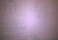
Something like this here circuit up here solved. So I can see if I'm doing it right. But I'd probably like to know how to use this here thing too.
So, I thought I had this nodal, with dependent voltage source cracked. I went and tried to find a few solved examples, however it's surprisingly difficult to find something that matches what I need. Also many that the commentators are saying the people in the videos are definitely wrong.
PANIC ATTACKS - 4 days to go till exam... not good
A older student recommended I try multisim and loaned me his multisim13 version.
A great tool indeed. Though I'm struggling with these controlled voltage sources.
Pulling the wires round all sorts of spirally crazy directions, I just don't like it... and I'm not entirely sure i'm doing it right.
So I found out about the AMB
I wanted to design the circuit in this thread
https://forums.ni.com/t5/Multisim-and-Ultiboard/Current-Controlled-Voltage-source/td-p/2867600
Now I have no idea what the heck this means
5*(V(1)-V(0))/2
When I first researched this ABM it seemed to me that - you could click on the piece of wire you wanted the current from. Call it something in "preferred net name" say for eg. " i "
Go to the value of your ABM 5(i). Boom dusted...
I mean how simple would that be ?
But no... sigh...
You know all I need?
Something like this here circuit up here solved. So I can see if I'm doing it right. But I'd probably like to know how to use this here thing too.
")


