Hello to everyone. As much as I know, directions for currents in the nodal analysis are chosen arbitrarily, however, for different directions chosen, I get different answer. What directions should I use and why?
As you say, it doesn't matter what directions you assign -- you just need to use them consistently.
Having said that, classic nodal analysis does not assign a fixed direction for the current in a branch. Instead, the directions of current are temporarily assigned as each node equation is developed. Traditionally, all currents are assigned as leaving the node and the equation is then formed by setting the sum of currents leaving the node to be zero. A modest enhancement of this is that on the left side the sum of currents flowing through components such as resistors is set equal to the sum of current flowing into the node from current sources on the right.
In your first attempt, you have i1 and i2. But you set
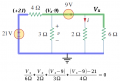
i1 = v2/6Ω
i2 = v2/3Ω
But i1 is flowing toward node V2 while i2 is flowing away from it.
Your KCL equation is correct, reflecting the assigned directions for the currents. But now you need to develop the proper equation for each current that also reflects that assignment.
i1 = (0V - v2) / 6Ω = -v2/6Ω
Notice that this assumes that the bottom node is 0 V, something that you haven't indicated. Always indicate your common reference node (often known as "ground").
This is nodal analysis, so forget about currents and work with node voltages (unless the circuit actually has a current source.) Before writing the node equations one needs to prepare the circuit diagram for nodal analysis:
1 - Identify the reference node (if not already done for you).
2 - Color-code the nodes and supernodes.
3 - Label the node voltages.
4 - Label the supernode voltage offsets.
5 - If there are dependent sources, express the control variable in terms of the node voltages.
6 - Mark the control variable expressions on the circuit diagram.
7 - Write a node equation for each node or supernode; except the reference node or ground-supernode. All the information necessary to write a node equation will be clearly displayed on the circuit diagram.
There is more than one way to form the node equations, but the most important consideration is to do it exactly the same way every time. Being consistent will remove any uncertainty about the result. Nodal analysis is a procedure, so follow the procedure. The great object is to substitute consistent procedure for making assumptions on the fly which may be different for every problem. Making assumptions is just another opportunity for making errors. Note that understanding what the circuit is doing is optional because correctly following the procedure will yield equations that describe what the circuit is doing. However, I believe there is one method that will reduce the errors that can be made and will make it easier to track down those errors.
Do it this way: Every term in the node equation begins with the voltage of that node, so each term has the form (Node Voltage - Adjacent Node Voltage)/(Resistance to Adjacent Node). One consequence of using this form is that current leaving the node is considered positive, so this determines the sign of any current sources attached to the node. For each node equation, sum all the pathways to adjacent nodes and set it equal to zero.
 Facebook
 Google
 GitHub
 Linkedin