NKK Led Switch Part # UB-16S

Thread Starter

arishy

Joined Apr 26, 2014
128
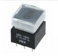
This is 5 pin switch
Two in the back and Three in front Let us number them clockwise 1,2,3,4,5

The Specs: 5A 125v 250v

1 & 2 open circuit
Pushing the switch to affect 3,4,5
3 is common when up 3 and 5 connected
when down 3,4 connected
In the picture attached the 3 pins are 3,4,5 right to left

The question:
How to wire it to indicate if 250v AC is on, LED on by pushing down
And what is the function of 1&2 ...are they for L & N of the 240v AC. Does polarity matter ( for the LED)
 

Attachments

Audioguru again

Joined Oct 21, 2019
6,826
The schematic of the switch shows that the LED is completely separate from the switch. "The LED is isolated and requires an external power source".

Use the two-poles switch with one pole switching the AC and the second pole for switching a DC voltage through a resistor to the LED. Of course the LED must have the correct DC polarity and current limiting.
 

Thread Starter

arishy

Joined Apr 26, 2014
128
Mine is UB-16S with 5 pins
According to your datasheet. the FRONT 3 pins are used for controlling the 240v (NC/NO)
so I assume the BACK two pins are for the LED. Is that correct? If yes what value for the external power source? Is it a normal led with say 5 v and 330 ohm resistor?

I still do not know how to connect the 5 pins Help is needed.
I assumed a much simpler use. By that I mean; providing the source of 240v and the led will activate automatically ( wishful thinking on my part)
 
Last edited:

sagor

Joined Mar 10, 2019
1,047
The LED is totally separate (and should be labeled as +/- or L+/L-). You have to provide the current to illuminate it on your own, it is not integrated with the switch.
The datasheet says forward current of 20ma, but usually 10ma will do just fine. A 5V source and a 330 ohm resistor should light it up ok.
 

Thread Starter

arishy

Joined Apr 26, 2014
128
The LED is totally separate (and should be labeled as +/- or L+/L-). You have to provide the current to illuminate it on your own, it is not integrated with the switch.
The datasheet says forward current of 20ma, but usually 10ma will do just fine. A 5V source and a 330 ohm resistor should light it up ok.
Thank you for your response.
The idea is ( at least the way I understand it) if you press the button BOTH 240v is applied AND LED is on to indicate that you have power. I do not believe THIS happening if I do the EXTERNAL wiring for the LED.
 

Audioguru again

Joined Oct 21, 2019
6,826
The manufacturer's datasheet for the switch shows and explains that its LED has nothing to do with the switch turning it on or off.
The LED is probably supposed to be lighted all the time so that you can see the switch in the dark.
 

Thread Starter

arishy

Joined Apr 26, 2014
128
The manufacturer's datasheet for the switch shows and explains that its LED has nothing to do with the switch turning it on or off.
The LED is probably supposed to be lighted all the time so that you can see the switch in the dark.
Thank you for your comment. Common sense is not that common !!!! after all
 

Tonyr1084

Joined Sep 24, 2015
9,744
Provided this is a latching switch, the LED is lit by circuitry the person designing the circuit must account for.
How to wire it to indicate if 250v AC is on, LED on by pushing down
IF you're going to use the 250VAC to light the LED there are a few important ways to accomplish this: First, the LED can likely NOT withstand 250V reverse current, so you will either need to provide an alternative pathway OR use a diode in series blocking the reverse current. Using a resistor to limit a super bright LED to 10mA would require a very high resistance. At 250V it's not critical to calculate for the LED's forward voltage drop (Vf). Using mains power to light the LED would require a 25KΩ resistor rated for a minimum of 2.5 watts. I would either use a 3 watt resistor or even a 5 watt. That's a fair amount of heat energy to consider.

If, on the other hand, you have a power supply that runs on 250VAC and provides - for example - 5VDC then you can use a 330Ω resistor for 15mA through the LED without the need for any reverse current protection.

To address all your needs it would be helpful to know more about how you plan on using the switch. Again, assuming this is a latching switch - the LED can indicate power status. If it's a momentary switch then the LED would only light up when pressing the button. OR switch off when pressing the button, depending on your design. So if you need more help - help us help you. Be specific in your intended use and presumed methodology for lighting the LED. We can get you there.
 

Thread Starter

arishy

Joined Apr 26, 2014
128
Provided this is a latching switch, the LED is lit by circuitry the person designing the circuit must account for.

IF you're going to use the 250VAC to light the LED there are a few important ways to accomplish this: First, the LED can likely NOT withstand 250V reverse current, so you will either need to provide an alternative pathway OR use a diode in series blocking the reverse current. Using a resistor to limit a super bright LED to 10mA would require a very high resistance. At 250V it's not critical to calculate for the LED's forward voltage drop (Vf). Using mains power to light the LED would require a 25KΩ resistor rated for a minimum of 2.5 watts. I would either use a 3 watt resistor or even a 5 watt. That's a fair amount of heat energy to consider.

If, on the other hand, you have a power supply that runs on 250VAC and provides - for example - 5VDC then you can use a 330Ω resistor for 15mA through the LED without the need for any reverse current protection.

To address all your needs it would be helpful to know more about how you plan on using the switch. Again, assuming this is a latching switch - the LED can indicate power status. If it's a momentary switch then the LED would only light up when pressing the button. OR switch off when pressing the button, depending on your design. So if you need more help - help us help you. Be specific in your intended use and presumed methodology for lighting the LED. We can get you there.
Wow, thank you for your extended remarks.
My objective is EXTREMELY simple. I want to wire the switch ( it is a LATCHED switch) to 240v volt AC and I need to know is the power is on with the help of the "Internal Led" ...Simple ...Do you agree?
Now from what I understood based on this post's responses; The LED is NOT linked to the mechanical action of the switch.
So; what I decided is: to provide 5v to the led BASED ON THE 240v; when I push the button DOWN. The 240V will be converted to 5 v dc and lit by the LED. I hope my explanation is clear enough. ( I am trying to help you to help me)
 

Tonyr1084

Joined Sep 24, 2015
9,744
My objective is EXTREMELY simple.
I agree. Assume your LED indicator has a 2Vf (Vf = Forward Voltage). Your 5V supply - minus the Vf equals 3 volts. Assume you're intending to run the indicator at 10mA. 3V ÷ 0.01A = 300Ω. When you turn on the switch it will power whatever it's hooked to including the 5V wall wart. HOWEVER! When you shut it off the wall wart will likely have a reserve voltage that may keep the LED lit for several seconds after shutting things off. You may want to include a resistor across the output to drain the residual power. However, that can be wasteful and produce excess heat.
1649338660112.png
 

ThePanMan

Joined Mar 13, 2020
862
There's a way without using a wall wart. You will need a diode, probably a 1N4007 in series with your LED oriented the same way as the LED, and use either a 3 watt or 5 watt resistor at 24KΩ. This will limit your LED indicator to just about 10mA without the need of an additional power supply that could fail. And like @Tonyr1084 said, with a wall wart, when you turn them off there's smoothing caps in the output circuit that will hold some charge for some few to several seconds. This way (below) you won't have that problem.
1649350311450.png
 

Delta Prime

Joined Nov 15, 2019
1,311
Hello there :)
( I am trying to help you to help me)
I would like to help you not to kill yourself or burn your house down.
And what is the function of 1&2 ...are they for L & N of the 240v AC
1649406100628.png


According to your datasheet. the FRONT 3 pins are used for controlling the 240v (NC/NO)
How do you plan on connecting all three pins to 240VAC I only say this because there is a conflict in your statements.
The Specs: 5A 125v 250v
that is the limit of your switch...but is that for five amps at 125V or 5 amps at 250V?
To address all your needs it would be helpful to know more about how you plan on using the switch
Please answer Mr. @Tonyr1084
Question.
My concern is safety!
 

Tonyr1084

Joined Sep 24, 2015
9,744
Please answer Mr. @Tonyr1084
Question.
My concern is safety!
The drawing I gave you shows just one of the 240V lines connected to the common pin of the switch. The NO (Normally Open) pin is connected to whatever it is you're controlling. Since the switch is rated for 240V it should be OK, provided you're within the capability of handling the amount of current your controlled device is going to use. That 240V is also providing power through the switch to a wall wart providing 5VDC. That 5V is used to power the LED.

As far as safety concerns, you need to be able to work with the circuit WITHOUT POWER! I'll say that again so you don't think maybe I meant something else - WITHOUT POWER. The breaker needs to be shut off - OR if you're using a plug in device the plug MUST BE UNPLUGGED. Pay attention. Working on 240VAC while powered is extremely dangerous. I've never been shocked by 240 but I hear it hurts like hell.

Now, having said that as clear as possible - and I don't assume you're not bright enough to figure that out on your own - I never know what level of experience and capabilities ANYONE who may read this is competent of. So please don't think I'm speaking down to you. Or anyone else. It's just that 240V is some serious power - and danger.

OK. Safety: How you enclose the project is important. There needs to be no way of accidentally contacting live circuits when operating. There needs to be no sharp edges that wires can chafe and cut through the insulation, presenting a shorting or shock hazard. The case, if metal, MUST be grounded. I say "Must" but I mean "Should". But I still say "Must" because it's important to not neglect that aspect of safety. A highly recommended protection device such as a fuse IS Highly Recommended. It should be rated high enough to handle the circuit needs while not being so high as to present an overload condition that could start a fire. If the switch is rated to handle 10 amps then you should use a 10 amp fuse. In the event your controlled device shorts out rather than weld the switch closed (conducting) the fuse will burn out first. If there were no fuse then the switch contacts could weld closed and when you think or expect power to be off you could get a horrible surprise. And if no fuse - your project could draw full amperage causing a potential fire.

I'm confident I've covered MOST of the safety concerns here. However, because as often happens, I missed a point or two, others will quickly point out other things that may have been overlooked. So I'll repeat my question from post #9
To address all your needs it would be helpful to know more about how you plan on using the switch.
Allow me to be as clear as I can be - exactly what is this project of yours going to control? The reason why I ask is because if we know you're planning on using a 2 amp switch to control a 500 amp circuit - I exaggerate for emphasis - we can stop you. You DID say "My concern is safety!" Hence, we can help you be successful AND safe - IF we know what you're doing. Again, this isn't assuming you're an idiot - no. This is in the event some idiot (not you) should read this and THINK he/she knows all they need to know; and then end up getting hurt - or worse.
 

Tonyr1084

Joined Sep 24, 2015
9,744
There's a way without using a wall wart. You will need a diode, probably a 1N4007 in series with your LED oriented the same way as the LED, and use either a 3 watt or 5 watt resistor at 24KΩ. This will limit your LED indicator to just about 10mA without the need of an additional power supply that could fail. And like @Tonyr1084 said, with a wall wart, when you turn them off there's smoothing caps in the output circuit that will hold some charge for some few to several seconds. This way (below) you won't have that problem.
View attachment 264496
Thanks Pan, but I'm not really a fan of this method. Yes, it will work, but you're asking the TS to work with dangerous voltages. Again, yes, it will work, but I like the approach of using the wall wart instead of dropping almost 3 watts of heat inside some enclosure we have yet to find out more about.

I realize, now that you mention it, when you turn off a wall wart there's a voltage still present as the capacitors discharge. I have a 20 amp 13.8V supply that when I turn it off it will still light an LED for quite a few seconds beyond shutting it off. Yes, that could confuse the operator. They switch the device off but the indicator light continues to glow, confusing them to thinking they didn't shut it off. Someone could get hurt if a machine is still running and they stick their hands into a dangerous place. I'll modify my drawing to show an additional load resistor to drain off excess power more quickly so the LED goes out faster. However, I can't predict just how fast the LED will shut off because I won't have any way of knowing what the wall wart is capable of doing. I'll be back in a few minutes with an updated drawing.
 

Delta Prime

Joined Nov 15, 2019
1,311
However, because as often happens, I missed a point or two, others will quickly point out other things that may have been overlooked
My post in this thread was addressed to the thread starter.You missed and overlooked not a thing. When I read someone wanting to connect a switch to 240VAC I automatically think home appliance. Unless otherwise stated.
You were spot on! Sir... :)
 

Thread Starter

arishy

Joined Apr 26, 2014
128
My post in this thread was addressed to the thread starter.You missed and overlooked not a thing. When I read someone wanting to connect a switch to 240VAC I automatically think home appliance. Unless otherwise stated.
You were spot on! Sir... :)
I do appreciate your wonderful support and concerns. The switch will be used with its specs in mind ( 125-250 5Amp) as stated in the beginning. This is taken from the datasheet directly.
To be safe I will use a switched type adapter because of its isolated dc portion.
 
Top