Night rider effect with 15 segments

Wendy

Joined Mar 24, 2008
23,797
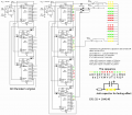
One thought about the parallel resistors, all those pesky variations go away, and settle down to a nice boring math function of RC.

Either way, sounds like fun.

I haven't located the invoice yet, it will turn up about the same time your LED do I suspect. I also suspect the culpret is customs, lets hope none of them need blue LEDs.
 

Thread Starter

Fenris

Joined Oct 21, 2007
288
Hi Bill

Yes it gets a bit easier :D Ah customs............I'll watch out for a car sporting far to many blue LED's :D

My mate is pretty impressed so far :)

regards

Fenris
 

Thread Starter

Fenris

Joined Oct 21, 2007
288
Oh Lordy!

My mate needs the unit done and installed by the 4th of september :D . No pressure then. But His Dalek Storm, who is getting the unit, is going to be meeting Nick Briggs (voice of the Daleks) and Series writer Gary Russell!!!!!!! I thrive under pressure!!!

regards

Fenris
 

Thread Starter

Fenris

Joined Oct 21, 2007
288
Hi all

All the parts arrived today :D So I nipped out and had the toner transfer patterns done for the main board and the 15 LED modules. I also had some other projects printed as well for after ;)

Here they are post etching and requiring only drilling and cleaning. The LED modules also require cutting into their seperate pieces. There's 18 I only need 15.

For scale the numbers on the main board are only 1.5mm tall.

regards

Fenris
 

Attachments

Thread Starter

Fenris

Joined Oct 21, 2007
288
Well so far so good. The main board is built and initial tests show a signal present at all the points as it passes back and forth. Next up will be a test to ensure the back and forth sweep action I want is correct in it's sequence.

I will do this by setting up 15 standard LED's with resistors on a bread board wire up between the circuit and the board and hopefully I will be greeted by the 'knight rider' pattern.

Tomorrow will also be the day I construct the 15 LED modules with the 3 LED's, 1 transistor and a capacitor each.

Interconnects between the LED's and the main board will be a 15 way D connect plug and socket and a 2.1mm DC socket for the power lines between the 2.

Here is a picture of the main PCB, finished.

regards

Fenris
 

Attachments

Thread Starter

Fenris

Joined Oct 21, 2007
288
A serious brown trouser moment ensued upon conducting the test of the main board. Like no lights. A quick check showed the timer was giving out the signal and individual tests of each output showed an output.

I then realised that it seemed to be a bit of a 'one shot'. Further tests showed that the outputs of U2/U5 seemed a bit off. Only firing once and indeed pin 3 (output 0)didn't fire at all.

There followed much wailing and gnashing of teeth. Then I got on with trying to identify the problem. It took a little while to nail it but using the schematic and my PCB pattern I eventually found I had made a slight boo boo.

U5 Pin 13 (Inhibit) should go to ground.................FAIL! I had left it unconnected :( So I corrected the PCB pattern first :D Then dropped a piece of wire into place on the board. Checked OP 0 (pin 3) and it was live.

So slapping the board onto the bread board I hooked up the outputs to the LED's I'd laid up on the board, strapped the battery in place and nothing................... AH! lok the battery wire has frayed and come off!!! Fixed that then tried again.

Success!!! 15 red LED's glowing backwards and forwards :D PHEW!

http://s200.photobucket.com/albums/aa97/Fenris_2007/?action=view&current=SV600313.flv

Next up the LED modules!!!

regards

Fenris
 

Thread Starter

Fenris

Joined Oct 21, 2007
288
Cheers :)

I am just building the LED modules. I have 5 Red at the moment and have tested 1 on the board. All is well :D

Only 10 more to make!

One minor but important question -> If I forgot the base resistor (10K) how much trouble would I be in? IE what are the implications for the longevity of the unit?

regards

Fenris
 

Wendy

Joined Mar 24, 2008
23,797
If it is the delay we were talking about I don't think I showed a base resistor. I'd have to see the current schematic to be sure, but I don't think it will be a big deal for a common collector design.

I have hopes of RGB diodes getting cheaper over time, they are 4 lead devices in a conventional 5mm LED package that (in theory) can do any color that exists. To me that seems to have possibilities.
 

Thread Starter

Fenris

Joined Oct 21, 2007
288
Hi Bill

It's looking good :D I had 2 of the modules up to play with and it looks great!
The base resistor question comes about because I actually forgot to make provision for it on the LED modules :D . I can of course wire them in line if needs be but if I can get away with it then great ;) .

The multi colour LED's will/would be fun to have a play with. Pretty colours cycling randomly in a relaxing type fashion. Heres to the price falling sometime soon.

Interestingly I have had first hand example of the voltage not being enough :D.

Currently 9V runs the unit with it's single standard red LED's per OP. If I any modules in the line up they don't light up. 12VDC in and they do. I am correct in this being the Vf total of the LED's requiring a higher DC input or at least if my 9V battery is a tad flat then there isn't enough to drive the Vf of the LED's?

Heres a quick vid with 3 of the modules in line :D it's gonna be great!

http://s200.photobucket.com/albums/aa97/Fenris_2007/?action=view&current=SV600314.flv

regards

Fenris
 

Thread Starter

Fenris

Joined Oct 21, 2007
288
Forgot this schematic. Adjusted to reflect the missing base resistor. I can't wait to get this baby installed in it's final home.

regards

Fenris
 

Attachments

Thread Starter

Fenris

Joined Oct 21, 2007
288
Hi Guys

Thanks Audio. The diagram had a couple of ULN chips as drivers so the LED's had to go the other way round. I will correct the schematic little later.

Well I bit the bullet and have set the whole thing up. It works, BUT, there is a slight problem. one of the modules isn't functioning quite right. On startup the LED's start the sweep as expected. But module 13, which is driven by, Output pins 9 and 10 of U3 comes on then stays on at a slightly reduced brightness. They brighten when their turn comes round again but stay on.

I have rebuilt the module. In fact I had a catastrophic cock up and the original module was crushed by a large dog when I was trying to sort it. So i have built a new module with standard LED's for now and it does the same. I have even replaced the transistor just in case and the U3 chip just in case.
But all to no avail.

I have un soldered the signal wire and used it elsewhere and it triggers any of the other modules fine. So it has to be the module thats at fault. Transistor again??............... I just cut the transistor off at the legs and held another in place....Transistor was duff. :(

Ideas would be gratefully received as It's such a simple circuit I can't see what else could be wrong.

Bill. It would be interesting if the did 'borrow' it. One of our forum guys has already had his 'borrowed' for use in the 'Stolen earth' season finale :)

Heres a vid of the unit thus far.

http://s200.photobucket.com/albums/aa97/Fenris_2007/?action=view&current=SV600315.flv

regards

Fenris
 
Last edited:

Thread Starter

Fenris

Joined Oct 21, 2007
288
Hi All

Bill. For some inexplicable reason I have just cottoned onto the fact that I have done the modules with LED's in series rather than the parallel version that I bread boarded. :D It still works fine as far as fading time although I have to use a larger uF to get the same timings.

22uF are now fitted. Looks pretty good to me. So either method is a winner subject to the pro's and cons parallel or series LED's.

Regards

Fenris
 

Wendy

Joined Mar 24, 2008
23,797
I have a couple of mutts myself. When dogs and cats collaborate, the house and everything else suffers. My cat (left by my girl when she fled the nest and was raised by a very maternal bitch) was determined to dig through the wall, in spite of water bottles or anything else I could use. It wasn't too bad until the other dog decided to show him how it really should be done (which suited the cat just fine, more blame to spread around). I now have a substantial chunk of dry wall to fix, dangit!

The flip side is I'm pretty sure the dogs (both are over 60 pounds) have discouraged burglars, so it balances out.

I missed the parallel LEDs too, for what it's worth. The good news is the battery will last a little longer, as it will draw less current. The con is it will be more sensitive to battery voltage.

If you need any other specialty LEDs or transistors in quantity (or any other hard to find items) just ask.

Just finished this article, Submission, CMOS 555 Long Duration LED Flyback Flasher. It's something you might use someday. Take a look and let me know what you think.
 
Last edited:

Thread Starter

Fenris

Joined Oct 21, 2007
288
Hi Bill

Our 2 Dogs also give good service as a deterrent to any would be thieving types. Casper, the leader, is very good at opening doors. Especially when we are out and she decides to hunt for any of the kids sweets/biscuits :D . Bess, the second, just follows then joins in the snack!

I have been tidying up the PCB design and the schematic today. Is it worth putting it in the 'projects collection'? I have done both the parallel and series modules as well.

It will be running of a 12VDC supply, namely, a car battery. So hopefully all will be well. I've had it running for around 12 hours and it still makes me smile :D

So next up, between decorating chores, is the 4 20 x 2 :)

I like the fly back. I might just build it for fun :D I have only wound one coil and that was for a radio that didn't work for whatever reason. So having another go will be interesting.

regards

Fenris
 

Wendy

Joined Mar 24, 2008
23,797
I think any finished project is worth posting in the projects collection, especially with pictures. People learn from each other, and you never know who will pick what up. Beside, I think a lot of us find your projects pretty neat.

My flyback flasher is still going strong, along side the blue LED flasher. Looks a little like someone has been pulled over in the living room in the dark, those LEDs are pretty bright. To be honest, I was a little surprised with the efficiencies, I knew it would work, it just works better than I thought it would.

If they weren't so parts intensive they could be an answer for some of your projects, it would be nice to have a random 20 LED flasher that lasted almost a week continuous off a couple of AA batteries.
 

Thread Starter

Fenris

Joined Oct 21, 2007
288
Done. Just have to wait for approval :) . The random 20 LED's on a couple of AA cells sounds good especially if it lasted a good while.

Just one quick question on the 4017 circuit - On switching on the unit 2 of the modules come on and only get into the rhythm after a couple of sweeps. This is to do with not having a cap/resistor to reset the whole unit at startup (I think)......where would I put the needed bits?

regards

Fenris
 
Last edited:
Top