Night rider effect with 15 segments

Thread Starter

Fenris

Joined Oct 21, 2007
288
Hi Bill

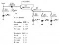
Well. It looks like this is all set to roll then. Luckily I have a pack of mixed caps and there are enough of the spec you have suggested. I'm likely to build the main PCB because thats a foregone conclusion I think/hope :D The LED's I can bread board with a suitable darlington to check the function and fiddle the fade effect.

I have looked up the specs for the NTE46 that Bernard referenced.

Vces = 100V
Vcbo = 100V
Vebo = 12V

Lc = 500mA

The nearest similar I can find with the suppliers I use all have a Vebo = 5V but are the same on the other specs. Any advice on what I should use? A range of options would be good as there seems to be a minimal choice at rapidonline.

regards

Dave
 

Wendy

Joined Mar 24, 2008
23,421
I'd definately wire a simple single LED (OK, maybe not one LED, but one segment) version first, just as a concept check.

Dang, that was a quick reply. I figure it is 7PM your time, so I guess I shouldn't be surprised.
 

Thread Starter

Fenris

Joined Oct 21, 2007
288
:D

Speedy here! I'll do that, it will be quicker to prove the LED module wont it. Can you recommend a darlington by spec for me please then I can track down suitable candidates from those listed with rapid and cricklewood.

regards

Fenris.
 

Thread Starter

Fenris

Joined Oct 21, 2007
288
Heres a pic showing the LED module redesign. 2 versions the 6 LED is the expanded module the 3 LED is likely to be the one used but until I get to measure the slates and see how the light module performs in situ I'm hedging my bets :D .

regards

Fenris
 

Attachments

Wendy

Joined Mar 24, 2008
23,421
My standard is TIP101, but I'd go with whatever is in your area. Remember, you can make Darlington pairs yourself (hence the name), so whatever is cheaper works.

Personally I'd think this is a job for a protoboard, no PCB needed at this stage. If you do just want to use a PCB, don't forget to allow for several capacitors.
 

Bernard

Joined Aug 7, 2008
5,784
Reverse engeneering NTE catalog, 'came up with:
NTE46,Hfe 10000, .5A = 2N6426, 2N6427, MPS5305, MPS5307, MPS5308, MPSA25, MPSA26 &27,28,&29
NTE48[ giant TO 92] Hfe 25000,1A; = 2N6724 & 25, MPSW13 &14,,45,45A
NTE172A,Hfe 7000,.3A,TO92; =MPS-A12
The bigger Hfe, the smaller the cap. I wonder if ground side of caps were all tied to a common bus, bus tied to slider on pot, ends of pot to gnd. & +, then you could gang change cap charge to match delay with changing sweep rate?? More thoughts; on quad OP-Amps, tolerance is on resistors, not transistors, but it'late.
 

rjenkins

Joined Nov 6, 2005
1,013
Hi,
to get good LED control and fade-on / fade-off scanning effect:

Run the LEDS from 12v and the 4017 circuit from 5V.

Use a series resistor from the 4017 out to the base of a darlington transistor, with a capacitor from the base to 0V / ground.

Then also add a series emitter resistor. This makes the driver into a constant-current controller; with 5V to the base you will have about 3.5V at the emitter, so eg. using a 100 Ohm emitter resistor would give a 35mA constant current sink.
(Test and adjust on the final circuit).

The R-C network on the base sets the ramp-up & ramp-down time to give the fade effect.

If you are using more than one chain of LEDs per output, add a 10 Ohm resistor per chain to balance the current, otherwise no further limiting needed.

I use the 5V Drive / emitter resistor constant current system on commercial LED controllers, however I use PWM to control the channel currents rather than the R-C circuit.

For the RC values, I'd guess 1K and somewhere between 10 - 100uF or 10K and 1 - 10uF. It depends on the 'scanning' speed and how you want it to look.
Again, trial an error to get the best appearance.

If you go too high on the resistor, it will reduce the base voltage and therefore the drive current. Too low and the 4017 outputs will limit the current.
Too high on the cap and you you won't reach full brightness before it switches off again.

Not having looked at the 'scanning' circuit, if you have diode logic before the outputs I'd use buffers (sections of 74HC244 ?) to drive the output circuit rather than the diode logic, so the outputs are 1:1 with the RC circuits and each always gets the same drive.

Note: For this to work, you MUST use descrete darlingtons (TIP121 rings a bell). IC Darlington drivers have internal resistors which will stop it working.
 
Last edited:

Thread Starter

Fenris

Joined Oct 21, 2007
288
:eek: Theres a lot going on isn't there! Thanks for all the input guys.

Side stepping slightly here because this is also a learning thing for me. Transistors -

I know the basics. Voltage/current at the base allows a circuit through the collecter/base. Use as a switch or amplifier. That bit was easy if concise.

I was reading Forrest Mimms, last night, about transistors. Standard transistors are current devices?

So you use a base resistor to adjust the current at that point to keep the current flow within tolerance of the collecter/emitter?

Rjenkins you say a setup the 4017's with a 5V supply. Is this because the Darlington you suggest has an absolute maximum emitter base voltage of 5V?

Then the absolute maximum base current is 120mA. So you factor in the base resistor to get the current in range but select for headroom of course?

At this point if I haven't missed the mark totally I start losing it. How do you know that you get around 3.5V at the emitter?
I have been advised on the deducting voltage across a device from the supply voltage before. This is the same isn't it but I can't see how you worked it out. I am reading up on transistors but everyone insists on greek letters and lots of equations I just want to know how to work out how to pick a transistor to do a job........and how did you know???

One minor breakthru. I understand that you took the 3.5V then /100Ω to give you the 35mA at the base. VIR 101 :D

OK then the current is well under the max for the base. I find that the hfe is 4 from the data sheet for the 'small signal current gain'.............. so 35ma x 4 will net 140mA across the emitter collector??? Large blank then follows as to how is this important but if the Vf of one group of LED's is 6.6V I though any voltage below that would mean no lights so how does the 3.5V work...................I'm getting one of my headaches.

Lots of questions I'm afraid but gradually little bits are being filled in.......I'll be about 90 before I can do anything with it like but a day where you learn something isn't wasted.

regards

Fenris
 
Last edited:

Wendy

Joined Mar 24, 2008
23,421
Hi,
to get good LED control and fade-on / fade-off scanning effect:

Run the LEDS from 12v and the 4017 circuit from 5V.

Use a series resistor from the 4017 out to the base of a darlington transistor, with a capacitor from the base to 0V / ground.

Then also add a series emitter resistor. This makes the driver into a constant-current controller; with 5V to the base you will have about 3.5V at the emitter, so eg. using a 100 Ohm emitter resistor would give a 35mA constant current sink.
(Test and adjust on the final circuit).

The R-C network on the base sets the ramp-up & ramp-down time to give the fade effect.

If you are using more than one chain of LEDs per output, add a 10 Ohm resistor per chain to balance the current, otherwise no further limiting needed.

I use the 5V Drive / emitter resistor constant current system on commercial LED controllers, however I use PWM to control the channel currents rather than the R-C circuit.

For the RC values, I'd guess 1K and somewhere between 10 - 100uF or 10K and 1 - 10uF. It depends on the 'scanning' speed and how you want it to look.
Again, trial an error to get the best appearance.

If you go too high on the resistor, it will reduce the base voltage and therefore the drive current. Too low and the 4017 outputs will limit the current.
Too high on the cap and you you won't reach full brightness before it switches off again.

Not having looked at the 'scanning' circuit, if you have diode logic before the outputs I'd use buffers (sections of 74HC244 ?) to drive the output circuit rather than the diode logic, so the outputs are 1:1 with the RC circuits and each always gets the same drive.

Note: For this to work, you MUST use descrete darlingtons (TIP121 rings a bell). IC Darlington drivers have internal resistors which will stop it working.
I see where you're going, but the problem is he want the highest possible input resistance to the transistors. If you break it up as you suggest then the cap sizes will have to increase to compensate. Still, Fenris, while you're experimenting...

The other problem is the resistor chains Fenris is planning will be quite large in voltage drop. This could be a problem with either scheme.

If you examine this project closely Fenris doesn't want a fade on effect, just the fade out part. The LED lights as fast as possible, then slowly goes out.

Good point about the descrete darlingtons vs. integrated versions, I'd use two switching transistors and go that route.

I think rjenkins is wanting a cross between these two approaches.


A transistor can be set up as a constant current source. You program the voltage across the resistor, and whatever is drawn from emitter to ground in current is also on Vcc to collector, reguardless what the collector resistance is (unless the collector resistor is so large it can't reach the voltage required).

I'd go with what we talked about to start of, and see how it works. If you need to tweak it then you can. I think rjenkins make another valid point, LEDs don't respond to small current changes well. PWM may be required for a good visual effect, which ups the component count dramatically. We'll just have to try it and see. I've got some ideas on it though (of course). If this is needed the variation (and test selection) goes away, so it's not all bad.

Note to rjenkins, Fenris is sourcing a lot of info off my article, LEDs, 555s, Flashers, and Light Chasers.

You can see most of my stuff in Bill's Index
 
Last edited:

Thread Starter

Fenris

Joined Oct 21, 2007
288
Hi all

Yes indeed I am sourcing and being inspired by Bills articles. I currently have Bills 'from 4 20' circuit breadboarded and it will be getting made up with a home made PCB except its a twin 4 20. I am using 4 556's so in this instance I am actually doing a 'from 4 40' with all blue LED's :D Bill's articles have really lite the blue touch paper of electronics for me it's just a shame I have so much to learn :/

Bill is correct The LED's will come on straight away no fade required. In the spirit of experimentation I wanted to see if I could have them fade out. One of the things that will need doing is seeing if my mate wants the speed fixed or controllable as this would effect the size caps used. This would be of particular note at the extreme ends of the sweep as of course the LED's may not have faded next to the end group before being re lite.

This may not be a problem at all and may add to the overall effect of course.

Bill. I have just re done the original voice mod I made on vero board a couple of years ago from which my all singing and dancing one was born. I am re doing the layout and instructions for the thread on the project dalek forum and with this nice swanky vero board based software I have reduced the PCB size by 33% :O It looks a lot more ordered to :D Heres a pic. The black pen on the vero board underneath it is the original size. It's not finished yet just got to add the IC sockets, the IC's, 2 pots, mic, speaker and power. I am also trying out different cap values where I didn't have the specific value as I have read that you can go a bit wide of the mark in non critical circuits and they will still run. Should be interesting :D

regards

Dave
 

Attachments

Wendy

Joined Mar 24, 2008
23,421
Bill. I have just re done the original voice mod I made on vero board a couple of years ago from which my all singing and dancing one was born. I am re doing the layout and instructions for the thread on the project dalek forum and with this nice swanky vero board based software I have reduced the PCB size by 33% :O It looks a lot more ordered to :D Heres a pic. The black pen on the vero board underneath it is the original size. It's not finished yet just got to add the IC sockets, the IC's, 2 pots, mic, speaker and power. I am also trying out different cap values where I didn't have the specific value as I have read that you can go a bit wide of the mark in non critical circuits and they will still run. Should be interesting :D

regards

Dave
You would be surprised how many modern techs haven't learned that lesson. It was something I learned back as a teen, and still forget now and again.

I'm a zombie when I get home from work until I get some sleep. I would still wire two transistors to make a Darlington, but having gotten some rest I suspect that the original concept will work just fine, we don't need a slow fade, just something that lasts 1 to 4 clock cycles. I don't think intensity or a linear fade will matter a bit for the overall effect.

Have you started experiments yet?

Going through my personal cookbook I came across this. It approaches the same logic.


Modified, it looks something like this.

....................................................... or
......


The first will have more resistance, the second will probably last longer for the same capacitor due to the larger voltage swing. I'd go with the second myself.

My LED notes are in need of updating, I think.
.
.
.
 

Attachments

Last edited:

Thread Starter

Fenris

Joined Oct 21, 2007
288
Hi Bill

Technology waits for no man :D Thanks for taking the time to do the schematics. I have some of the parts to start trying the fade effect. I just need to get a couple of diodes for the output protection. I take it I need the 1N4001 to handle the backspike which the 1N4148's can't cope with? Need to get some transistors to. Lets hope maplins stock more than the usual 2 :D

My colleague is going to knock up a pattern for me of the louvers so I can see how the modules need laying up to suit.

I'll have to dismantle the 4/20 test unit to clear my bread board :( But I will be getting the toner printing done for that and the main PCB for this. It's all good good fun.

regards

Fenris
 

Wendy

Joined Mar 24, 2008
23,421
Naw, I used 1N4001's because that was on the original schematic. I go to a lot of flea markets. I bought a spool of 1000 1N4007 (higher voltage, but very similar) for $1.

Basically unless you are pushing the current or voltage specs, which this isn't, the exact diode type doesn't matter. At this frequency they are pretty much identical.

The exact transistor isn't too important either, any switching device will do. My personal default is the 2N2222 or 2N2907, when ever you see those you know it doesn't matter.

I've been buying protoboards for a long time, I have a box of them, starting with the one I built when I was in college (my folks machined a backplate for it). Sturdy sucker that one, it was run over by a car with no damage.
 
Last edited:

Thread Starter

Fenris

Joined Oct 21, 2007
288
Bugger they only have 3 in stock :( I will do an online order I think. I have 4 2N3904 transistors. Would these do to test out with regards to specs?

Those 2N2222A's ...............I haven't seen metal can transistor since I was a very young novice at this. In fact it was 2 BC107's used to make a flip flop circuit with torch bulbs :D

Just caught your last post. Cheers ;) The flea markets here just tend to have............well fleas. I'll have to look up and see if theres a local ham group or some such that may have meet and sales.

regards

Fenris
 

Wendy

Joined Mar 24, 2008
23,421
You want to see some cheap stuff check out Dan's Small Parts and Kits. It'll make you drool. I'm sure the EU has something similar somewhere.

I'm not sure about 2N3904, but I'm betting they will work fine. The current spec is the thing, 2N2222's come in PN2222 plastic packages. The original 2N2222 has a 0.6A spec.
 

Thread Starter

Fenris

Joined Oct 21, 2007
288
Im digging around and can only find the metal can 2N2222A over here. But I have set up an experiment.

One 555 timer to provide the trigger for the Darlington array as in diagram 2 using the 2N3409's.

Now initially The LED's stayed on. So I changed the cap to a lower value and upped the time period of the 555. This netted nothing except permanent illumination.

So I fitted an one LED of the output before the test setup to act as a reference for timing and with the cap removed from the Darlington setup the LED's came on and off as per the period set by the 555.

Insert the 'fade cap' and lights on all the time. Hmmmmmmm.

For some inexplicable reason I then did this. Bear in mind I have fitted everything as per convention and diagrams. I put the fade cap in with it's negative to the base of the transistor and the positive to ground........

A 1uF cap gives a fade duration of 3 seconds :D Yes it fades and in a nice steady fashion.

I have swapped one LED out for a blue one I had left over from the last project and this fades in around 1.5 seconds. This was mooted about the different Vf having a bearing on having to tune the LED's with different caps to balance the whole display.

I attach the schematic for reference to the cap orientation. I have found one 0.47uF and one 0.68uF cap in my bits box. The .68uF doesn't seem to do anything. But the 0.47uF gives a 0.5 - 1 second fade.

A quick check of what happens when orientating the cap as per convention and the diagrams. Reveals that the fade does happen but very slowly when compared to the speed of fitting the cap the wrong way round. Is this a useful way of getting more variations on fade speed? So the 47uF cap I first tried was taking so long to discharge and didn't even look like it was because the 555 was coming back on before the fade cap could decay to a level that could be seen visually.

I haven't had so much fun in years :D

regards

Fenris (well chuffed)
 

Attachments

Last edited:

Wendy

Joined Mar 24, 2008
23,421
You need smaller caps, much smaller. They aren't discharging through the transistor. With a conservitive gain of 10,000, and an estimated and adjusted emitter resistance of 530Ω, figure the base to ground resistanct is around 5.3MΩ. So a 1µF would yield around 5 seconds (1 RC constant). This is good, no? The caps can be much smaller, or you can put a resistor across the capacitor to bring this time down.

Or you can drop one of the darlington pair, and make it a conventional transistor and see what it does.
 

Thread Starter

Fenris

Joined Oct 21, 2007
288
Hi Bill

The smallest I have seen is 0.47uF. So a resistor across it's terminals may be an option as you say. I will also try a single transistor as well. This is very interesting to say the least :D

regards

Fenris
 

Thread Starter

Fenris

Joined Oct 21, 2007
288
Morning all

Well I have altered the setup to a single 2N3904. The 'fade cap' is now being fitted the right way round and it works a treat.

A 10uF cap gives a 0.5-1 second fade
A 22uF cap gives a 1.5 second fade
A 47uF cap gives a 3 second fade

These times are just based on counting rather than timing with a watch. All in all a very productive tinkering session. Thanks for all the input chaps, much appreciated!

regards

Fenris
 

Attachments

Top