Facebook
 Google
 GitHub
 Linkedin
Hi Guy's
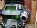
I've had a request for help with a project for a Special Weapons Dalek my friend has built. This is a fullsize, sit and drive prop. On the front of the shoulder section there is a vertical louver. There are 15 gaps between the louvers.
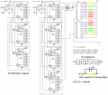
So the plan is to install a night rider effect chaser light. I have drawn up the 4017 circuit from Bills schematic which has 3 4017's connected. I have added a fourth 4017 to it so that there are enough outputs to cover the 15 slots.
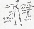
Now the only caveat is. 3 LED's per output so thats 45 LED's in total. Colours will be 5 sections red, 3 sections green either side and 2 sections yellow at each end. I am considering using an darlington array to act as the interface for the higher load.
The LED's will be super bright types as well. signal diodes will be fitted to the 4017's outputs to protect them from each other and a 1K resistor to the ULN2804. On the LED side I need to sort out the current resistor and how best to arrange each group of LED's (series/parallel) I have read parallel is bad and seen in Bills ebooks LED's arranged in series per channel.
I am also aware that due to the nature of the LED's that their behaviour will not emulate the fade effect of the filament bulb based circuit. That is unless I fit a capacitor across each group to cause the effect.
How do you calculate the current resistor value with LED's in series? Oh and it will be running on 12V
Heres a picture of the front of the shoulders. You can see the vertical slats where this project is to be displayed.
regards
Fenris
I've had a request for help with a project for a Special Weapons Dalek my friend has built. This is a fullsize, sit and drive prop. On the front of the shoulder section there is a vertical louver. There are 15 gaps between the louvers.
So the plan is to install a night rider effect chaser light. I have drawn up the 4017 circuit from Bills schematic which has 3 4017's connected. I have added a fourth 4017 to it so that there are enough outputs to cover the 15 slots.
Now the only caveat is. 3 LED's per output so thats 45 LED's in total. Colours will be 5 sections red, 3 sections green either side and 2 sections yellow at each end. I am considering using an darlington array to act as the interface for the higher load.
The LED's will be super bright types as well. signal diodes will be fitted to the 4017's outputs to protect them from each other and a 1K resistor to the ULN2804. On the LED side I need to sort out the current resistor and how best to arrange each group of LED's (series/parallel) I have read parallel is bad and seen in Bills ebooks LED's arranged in series per channel.
I am also aware that due to the nature of the LED's that their behaviour will not emulate the fade effect of the filament bulb based circuit. That is unless I fit a capacitor across each group to cause the effect.
How do you calculate the current resistor value with LED's in series? Oh and it will be running on 12V
Heres a picture of the front of the shoulders. You can see the vertical slats where this project is to be displayed.
regards
Fenris
Attachments
-
 175.1 KB Views: 157