Facebook
 Google
 GitHub
 Linkedin
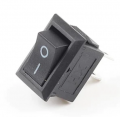
hi i would like to swap my 10k pot from a
https://fr.aliexpress.com/item/32859517196.html
attached file below 21.59.20
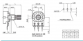
to a
https://fr.aliexpress.com/item/32624428063.html
21.58.37 file
I would like to know if they are exactly similar in the way they function? to avoid compatibility issues.
thank you
https://fr.aliexpress.com/item/32859517196.html
attached file below 21.59.20
to a
https://fr.aliexpress.com/item/32624428063.html
21.58.37 file
I would like to know if they are exactly similar in the way they function? to avoid compatibility issues.
thank you
Attachments
-
 133.2 KB Views: 15
 -
 130.5 KB Views: 15
![IMG_0842[1].JPG](https://forum.allaboutcircuits.com/data/attachments/239/239520-447083424c1182ad523a77aabff0e27c.jpg "IMG_0842[1].JPG")
![IMG_0843[1].JPG](https://forum.allaboutcircuits.com/data/attachments/239/239521-03afe295ba80a80d71fd2bdc2b0bd754.jpg "IMG_0843[1].JPG")