Newbie - help needed for basic HPF & LPF circuits

Thread Starter

cskerry87

Joined Sep 13, 2013
6
Hi all

Please excuse any etiquette mistakes - I have searched but not really found what I'm looking for.

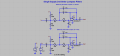
I'm wanting to create separate HPF and LPF circuits for use with electric guitar. From the research I've done, I can't really work out the disadvantages of a passive filter, which looks like it'd be pretty damn simple. However, it looks like any existing guitar filter circuits tend to be active, so I'm hoping someone can start me off with a basic design idea for an active filter.

I'd like them to have the following characteristics:

- 1 Megohm input impedance
- 10k ohm output impedance
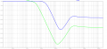
- Minimum 12db/octave rolloff (ideally 24db/octave)
- Variable cutoff frequency (using potentiometer) - the HPF should ideally be 20 hz to 300 hz, the LPF 20 khz down to 4 khz
- Ideally the output level (voltage) should match the input, or at least not be excessively higher or lower.
- Powered by 9v DC

If anybody could sketch a quick circuit for both, or point me towards something that would get me in the ballpark I'd be very grateful.

Thanks
 

Papabravo

Joined Feb 24, 2006
21,225
The reason you don't see passive filters for the audio range is because the required inductors have values that make their physical realization impractical.

Let us set aside the notions of impedance for the time being, and also the notion of using a potentiometer to change the frequency characteristics.

Some terminology:

LPF is Low Pass Filter. For an ideal LPF, the passband includes all frequencies from DC to some corner frequency where the response starts to rolloff at some number of dB/octave or dB/decade.
HPF is High Pass Filter. For an ideal HPF the passband starts at some positive corner frequency and remains constant up to infinite frequency
What you described in your post does not appear to be either an LPF or an HPF, but rather a bandpass filter. It has a passband between two frequencies and stopbands on either side.

Once you can define your requirements we can talk about the other issues.
 

Audioguru again

Joined Oct 21, 2019
6,691
Usually an electric guitar circuit has added severe high frequency distortion (fuzz) and overdrive (clipping).
Instead of filtering out the distortion with a filter, why not prevent the distortion in the first place?

Maybe the guitar player is slapping or hitting the guitar that causes low frequencies that you need to filter out? Simply prevent the player from doing that.

Why do you want to vary the cutoff frequencies of the filters? If the lowpass filter has a cutoff frequency too low then high frequencies will not be heard or will sound muffled. If the highpass cutoff frequency is too high then the low frequencies will not be heard or will sound "tinny".
 

Thread Starter

cskerry87

Joined Sep 13, 2013
6
Thanks all for the replies.

Some terminology:

LPF is Low Pass Filter. For an ideal LPF, the passband includes all frequencies from DC to some corner frequency where the response starts to rolloff at some number of dB/octave or dB/decade.
HPF is High Pass Filter. For an ideal HPF the passband starts at some positive corner frequency and remains constant up to infinite frequency
What you described in your post does not appear to be either an LPF or an HPF, but rather a bandpass filter. It has a passband between two frequencies and stopbands on either side.
Just for context - I'm a sound engineer, so I understand the definitions and differences between different types of filters on a conceptual level. I think my post maybe wasn't clear enough. Where I mentioned a range of frequencies (20 to 300 for the HPF), I was referring to the range of possible corner frequencies which I would like to be able to select with a potentiometer. I wasn't referring to a passband between those two frequencies.
 

Papabravo

Joined Feb 24, 2006
21,225
Thanks all for the replies.


Just for context - I'm a sound engineer, so I understand the definitions and differences between different types of filters on a conceptual level. I think my post maybe wasn't clear enough. Where I mentioned a range of frequencies (20 to 300 for the HPF), I was referring to the range of possible corner frequencies which I would like to be able to select with a potentiometer. I wasn't referring to a passband between those two frequencies.
Now that I reread the original post it seems that I misread what you were trying to say. I apologize for that. In order to understand what is going on with filters, it will take more than a few forum posts. Let us proceed to adjusting the corner frequency of a filter. In a passive filter you have a number of reactive elements (capacitors and inductors that have reactance) that determine the characteristics. The values are connected together to determine the filter characteristics like corner frequency, group delay, and rolloff. There is no single point of control in a passive filter that will allow for a potentiometer to control the corner frequency. In fact the filter may have no resistors at all. If you had a ganged variable capacitor it might be possible to change the capacitor values simultaneously over some range, but the problem is they don't make these things any more. Passive filters will also have an insertion loss of at least 6-dB assuming the source impedance and the load impedance are identical. With the mismatch you propose the insertion loss would be enormous. Think about a voltage divider consisting of 1 MegΩ and 10 Ω and you see the futility of this approach.

Moving on to active filters, especially for the audio range. Here the components are opamps, resistors and capacitors. Inductors in an active filter would be a rarity. Opamps do provide gain so it is possible to have no insertion loss or even some gain or attenuation. It is still the case that the filter characteristics are determined by the passive components. It is also still the case that in order to have an adjustable corner frequency you need to vary the value of all the components simultaneously and we unfortunately don't have a device that can do that.

What I can suggest is that you download a circuit simulator like LTspice. You can construct an active filter circuit and play with changing the component values to see the effect. This will probably be more helpful than a textbook on analog filters. If you have such a book great, but if not, don't worry, there are plenty of free resources on the web. Keep asking pointed questions, until you start to grok this stuff.
 

Thread Starter

cskerry87

Joined Sep 13, 2013
6
Maybe he wants the electric guitar to sound like it is being played through an old telephone line with no bass and no treble.
Nope. HPF's on guitars with cutoffs as high as 250hz are very common in studio and live sound. It cuts out unwanted hum, takes strain off the amplifier and makes space for the bass instruments in the mix. LPF's are also very common when you want to tame some of the fizz you can accumulate with distortion effects, as well as general high frequency harshness that some guitars produce. Electric guitars are a midrange instrument with not much useful content in the higher or lower frequencies, especially when you're trying to fit them into a full band mix.

HPF's & LPF's are also very useful for electric bass, again to make space in the very low end for the bass drum, and to cut out useless rumble, hum and top end fizz.
 

Thread Starter

cskerry87

Joined Sep 13, 2013
6
Now that I reread the original post it seems that I misread what you were trying to say. I apologize for that. In order to understand what is going on with filters, it will take more than a few forum posts. Let us proceed to adjusting the corner frequency of a filter. In a passive filter you have a number of reactive elements (capacitors and inductors that have reactance) that determine the characteristics. The values are connected together to determine the filter characteristics like corner frequency, group delay, and rolloff. There is no single point of control in a passive filter that will allow for a potentiometer to control the corner frequency. In fact the filter may have no resistors at all. If you had a ganged variable capacitor it might be possible to change the capacitor values simultaneously over some range, but the problem is they don't make these things any more. Passive filters will also have an insertion loss of at least 6-dB assuming the source impedance and the load impedance are identical. With the mismatch you propose the insertion loss would be enormous. Think about a voltage divider consisting of 1 MegΩ and 10 Ω and you see the futility of this approach.

Moving on to active filters, especially for the audio range. Here the components are opamps, resistors and capacitors. Inductors in an active filter would be a rarity. Opamps do provide gain so it is possible to have no insertion loss or even some gain or attenuation. It is still the case that the filter characteristics are determined by the passive components. It is also still the case that in order to have an adjustable corner frequency you need to vary the value of all the components simultaneously and we unfortunately don't have a device that can do that.

What I can suggest is that you download a circuit simulator like LTspice. You can construct an active filter circuit and play with changing the component values to see the effect. This will probably be more helpful than a textbook on analog filters. If you have such a book great, but if not, don't worry, there are plenty of free resources on the web. Keep asking pointed questions, until you start to grok this stuff.
Thanks for this.

I don't really understand why you say the cutoff frequency can't be altered without changing all component values simultaneously. I've seen RC filter calculators where, if the two capacitor values remain constant, a change of the resistor values will vary the cutoff freq. Looking at the filter below, could I not replace the two 110k resistors with a dual-gang pot, thereby varying them both at once and changing the cutoff freq?

Thanks again Filter.jpg
 

Papabravo

Joined Feb 24, 2006
21,225
It turns out that if you restrict yourself to 2nd order filters only that you can adjust the corner frequency if you can find a potentiometer that is actually two potentiometers in one. As the attached diagrams for the 2nd order lowpass show you can keep the capacitor values the same and vary the resistors from 562 Ω to 2.8 kΩ to cover 4 KHz to 20 kHz. You might be tempted to cascade two second order systems but adjusting them with separate dual-gang pots would be tricky and might produce unintended side effects.
 

Attachments

Last edited:

Thread Starter

cskerry87

Joined Sep 13, 2013
6
A great, that's what I was hoping for! I believe you can get what's called a dual-gang potentiometer, which is two pots in one body. That should do the trick.

Could you help me figure out how to set the input and output impedance for the above circuits? Also, how do I apply the power supply for the opamp? Is it as simple as a voltage divider to take the 9v DC input down to whatever the opamp is spec'd for?
 

Papabravo

Joined Feb 24, 2006
21,225
To do the impedance properly I need to see a schematic of the source and the load, to see if it is even necessary. The power supply for the opamp can be a battery, or a DC supply of any value that is between the limits on the opamp datasheet (3VDC to 15VDC). The one I picked for the simulation (LMC6484) is just a general purpose device and may or may not work for you. You have to check the datasheets -- carefully. Since you are going to have long wires from a PC Board to the pots you are going to be sensitive to noise pickup from a variety of sources. Alternatively you could mount the PC board to the pot. I do not recommend doing this on a breadboard unless it is a Manhattan style dead-bug construction.
 

Thread Starter

cskerry87

Joined Sep 13, 2013
6
Thanks again.

Without schematics off the top of my head, I can tell you the source would be a guitar's output, which is a very simple circuit consisting of an electromagnetic pickup and passive volume & tone controls. The output impedance is typically around 10k ohms to 15k ohms.

I understand that for audio circuits we want an impedance bridging setup, whereby the input impedance of the load is at least 10x the output impedance of the source, which minimises voltage drop. Therefore a typical input impedance for guitar processing circuits is 1meg ohm. Likewise the output impedance of the circuit wants to mirror the 10k - 15k ohms of the guitar itself, so that it can properly bridge to the 1meg ohm input of the next device in the chain.

I think with such a simple circuit I would aim to mount the pot on the board.
 

Papabravo

Joined Feb 24, 2006
21,225
Thanks again.

Without schematics off the top of my head, I can tell you the source would be a guitar's output, which is a very simple circuit consisting of an electromagnetic pickup and passive volume & tone controls. The output impedance is typically around 10k ohms to 15k ohms.

I understand that for audio circuits we want an impedance bridging setup, whereby the input impedance of the load is at least 10x the output impedance of the source, which minimises voltage drop. Therefore a typical input impedance for guitar processing circuits is 1meg ohm. Likewise the output impedance of the circuit wants to mirror the 10k - 15k ohms of the guitar itself, so that it can properly bridge to the 1meg ohm input of the next device in the chain.

I think with such a simple circuit I would aim to mount the pot on the board.
One of the benefits of the opamp active filter is that the input imepdance is very large with respect to the output of a low level source. In the case of your low pass filter the coupling capacitor for single supply operation will block all DC current. For the high pass filter the frequency setting capacitors will block the DC current. So I think you are good on the input side. The single supply highpass will also have a DC blocking capacitor so I think you are good there as well.
 
Top