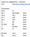
Newbie building 2-bit non-sequential counter using J K Flip Flop and struggling

WBahn

Joined Mar 31, 2012
33,021
I'm using a SN73LS73AN FF.

Sorry I thought I needed external inversion. Now I get it. The Q(bar) is already low.

I'll wire exactly as you showed. I just bought 2 x NPN and 2 x PNP transistors.

I assume from your drawing I tap from the 2 FF2 outputs and light the LED's via a transistor...?

Did this answer all your questions. Sorry I was confused but think I've got it now. I'm incredibly thankful for your help.
73LS73, or 74LS73? I'm going to guess the latter.

If you had the /CLR inputs tied to ground, that would explain the bulk of your problem as that would force the Q outputs HI (and the /Q outputs LO) for both flip flops regardless of any other inputs.

Note that the 74LS parts do not have very much drive capability. They are spec'ed only to be able to source 0.4 mA (when the output is HI) and sink 8 mA (when the output is LO). Furthermore, even with no load, the output typically only gets to about 3.5 V.

Finally, these parts are not rated to operate from a 9 V battery. The absolute maximum supply voltage is 7 V, meaning that ANY voltage above this can destroy the part (you usually have to go a bit above that, but there's no guarantee). The maximum operating voltage is only 5.25 V, meaning that if you put a higher supply voltage than that, but less than the absolute max, the part may not be damaged, but there's no guarantee that it will operate correctly.
 

crutschow

Joined Mar 14, 2008
38,609
I assume I tap from the FF2 Q(bar) to the base of a PNP transistor and the FF2 output to the base of a NPN transistor...?
No.
You want one transistor to connect to FF1 and one to FF2 to get the overlapping signals.
Q and Q(bar) from the same flip-flop are in sync, just inverted.

Since the SN73LS73AN can sink 8mA when the output is low, but can only source 0.4mA when high, the easiest is to use two PNP's with their emitters connected to V+ and about a 2k resistor between the base to the FF Q output(s).
The connect the LED resistor to the collector and the LED to ground.
Or if 8mA is sufficient LED current you can connect the LED and its resistor to the FF output and V+.
Heading back to the shops 10km away to buy a smaller battery pack.
The closest would be three NiMh cells in series to give about 4.5V.
Adding another cell would give 6V, which is too high.
 

WBahn

Joined Mar 31, 2012
33,021
Just try connecting your LED and series resistor pairs from +5V directly to the Q (or /Q) outputs directly. No transistors needed as long as your LED current isn't too high!
Not with a 74LS family part. They can't source much current (less than half a milliamp) and the output voltage isn't great to begin with (typically 3.5 V) and will get dragged down to about 2.5 V very easily.

If you ARE going to try to drive an LED directly, you need to sink current (connect the LED so that it is ON when the output it is connected to is LO) and you need to limit the current to no more than 8 mA (4 mA is a better design maximum).

Best to buffer the output with a transistor.
 

Thread Starter

shawn_from_melbourne

Joined Mar 17, 2023
14
I've connected and checked again and again. Using Q1 and Q2 outputs I get half an overlap then on the 4th pulse LED 1 comes back on but should stay off. Then I connected a 3rd LED connected to J1 and LED 1 and 2 worked correctly but the the 3rd was in a different sequence. I'm tired and need to look at this again after. Something isn't right. I will also swap the breadboard positions in case one of the connectors isn't connecting properly.

1679372313552.png. 1679372344140.png
 

sarahMCML

Joined May 11, 2019
703
Not with a 74LS family part. They can't source much current (less than half a milliamp) and the output voltage isn't great to begin with (typically 3.5 V) and will get dragged down to about 2.5 V very easily.

If you ARE going to try to drive an LED directly, you need to sink current (connect the LED so that it is ON when the output it is connected to is LO) and you need to limit the current to no more than 8 mA (4 mA is a better design maximum).

Best to buffer the output with a transistor.
That's what my suggestion would have done!
 

Thread Starter

shawn_from_melbourne

Joined Mar 17, 2023
14
I am puzzled it still doesn't work.
The only way I can make further useful suggestions is to see a complete schematic of your total circuit.
I have a replacement 74LS73 and I'm just about to put it all together. I'm running 4.5v now too and will use the transistors to drive the LED'S. Update coming soon.
 

sarahMCML

Joined May 11, 2019
703
I have a replacement 74LS73 and I'm just about to put it all together. I'm running 4.5v now too and will use the transistors to drive the LED'S. Update coming soon.
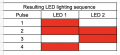
You should get the sequence as follows:
Led 1 on
Led 1 & 2 on
Led 2 on
Both off
Repeat
That's with your Leds both connected to EITHER (Q1 and Q2) OR (/Q and /Q2), NOT 1 of each.
EDIT: I'm driving high brightness led's straight of the Q outputs!
 

Thread Starter

shawn_from_melbourne

Joined Mar 17, 2023
14
So. Yes the IC's I had were fried. Replaced and cleaned up all the cluttering jumpers etc. Works.very nice now. Thank you for those who helped me put here. Now I want to use the outputs to drive 2 TIP41C transistors. I'm.working through the fundamentals of voltage drops and output from a TTL. Wanting to drive approximately 5amps across and looks like I need to fully saturate the transistor at 5v and output from TTL is only 3.65v. That should be enough as anything above 2.7v should be sufficient to switch. Anyway, I'm learning a lot here thank you everyone. Screenshot_20230329_132922_Gallery.jpg
 

WBahn

Joined Mar 31, 2012
33,021
Be sure to use current-limiting resistors with your LEDs. Ignoring this just because it seems to work today is a recipe for disaster.
 

MrChips

Joined Oct 2, 2009
34,982
I notice that you are using 74HC73 and not 74LS73.
These are different families of logic ICs and cannot be interchanged or mixed.

Also, be consistent with the colour of your wires, e.g. red for Vcc and black for GND.
 

Thread Starter

shawn_from_melbourne

Joined Mar 17, 2023
14
I notice that you are using 74HC73 and not 74LS73.
These are different families of logic ICs and cannot be interchanged or mixed.

Also, be consistent with the colour of your wires, e.g. red for Vcc and black for GND.
Thanks and yes. I ran out of jumpers. Even used a black marker on some.
I'll have to check on thr LS and HC differences. Thanks.
 
Top