New to soldering, how to solder mini USB connector?

Thread Starter

OneCircuitGuy

Joined Oct 14, 2020
17
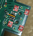
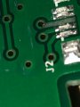
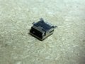
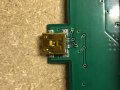
My friend has a broken blue snowball microphone and its powers by a mini USB cable plugged into a computer, the mini USB connector somehow broke off the board and has been rattling around its casing, I opened it up and found where its supposed to be connected, is this saveable? could I just solder the connector back onto to board somehow or possibly buy a replacement mini USB connector? is there any way of testing if it would work before I solder it? The pictures posted below are of the board where the connector should go, one of the connector itself, and one of me laying it how I believe it would sit on the board.
 

Attachments

narkeleptk

Joined Mar 11, 2019
558
Pretty simple for someone with a little experience. Probably easier to just drop by local phone repair place but if you want to try it yourself you'd prob be ok using the old usb port but I would still recommend a new usb port anyway. Do not pull that damaged pad/trace, Lay it flat to reuse or if its too delicate shape then just cut it off clean with a razor at that little circle. Scratch the green coating away (on circle) then run a tiny wire from that circle to the pin its suppose to connect with. I would probably place the tiny wire (or better copper tape) properly before placing the usb port to make it easier to connect.
 

Thread Starter

OneCircuitGuy

Joined Oct 14, 2020
17
Pretty simple for someone with a little experience. Probably easier to just drop by local phone repair place but if you want to try it yourself you'd prob be ok using the old usb port but I would still recommend a new usb port anyway. Do not pull that damaged pad/trace, Lay it flat to reuse or if its too delicate shape then just cut it off clean with a razor at that little circle. Scratch the green coating away (on circle) then run a tiny wire from that circle to the pin its suppose to connect with. I would probably place the tiny wire (or better copper tape) properly before placing the usb port to make it easier to connect.
Thanks for the fast reply and comment, do you think there's supposed to be the only one wire there? and I'm very new to soldering and working on electronics in general so what is this copper tape you are talking about and what kind would you recommend for this job? and if I used the tape would I still have to run the wire? and where would the wire go?
 

dl324

Joined Mar 30, 2015
16,909
Welcome to AAC!

It should be a simple repair for anyone who can solder.

I'd just straighten out and clean the lifted trace, lay it in it's proper place, install the USB connector making sure the lifted trace is under it's connector pin, solder the large ground connections to hold it in place, insure that the lifted trace is still under it's respective pin, solder the remaining connections.

Be careful when straightening out and cleaning the lifted trace so you don't make the problem worse. If you damage it, just remove the solder resist from the via it connects to and solder a short piece of wire to restore connectivity.
clipimage.jpg

The original problem was probably poor soldering and too much stress placed on the connector.
 

Thread Starter

OneCircuitGuy

Joined Oct 14, 2020
17
Welcome to AAC!

It should be a simple repair for anyone who can solder.

I'd just straighten out and clean the lifted trace, lay it in it's proper place, install the USB connector making sure the lifted trace is under it's connector pin, solder the large ground connections to hold it in place, insure that the lifted trace is still under it's respective pin, solder the remaining connections.

Be careful when straightening out and cleaning the lifted trace so you don't make the problem worse. If you damage it, just remove the solder resist from the via it connects to and solder a short piece of wire to restore connectivity.
View attachment 219639

The original problem was probably poor soldering and too much stress placed on the connector.
thank you for the reply! I can say this connector was probably put through a lot of stress, I made up a simple chart, is this chart correct of what I would do?
 

Attachments

dl324

Joined Mar 30, 2015
16,909
is this chart correct of what I would do?
I wouldn't bother with tape unless you damage the existing trace while cleaning and straightening. You should also remove as much solder as possible from the pads so the connector will sit flat.

If you use solder wick or a solder sucker to remove solder, make sure you do it from the edge side. The copper is held in place with an adhesive that will melt if too much heat is applied. You don't want to lift more copper and make the problem worse. But any competent repair person could fix it. It might not look good, but it would work.
 

Thread Starter

OneCircuitGuy

Joined Oct 14, 2020
17
I wouldn't bother with tape unless you damage the existing trace while cleaning and straightening. You should also remove as much solder as possible from the pads so the connector will sit flat.

If you use solder wick or a solder sucker to remove solder, make sure you do it from the edge side. The copper is held in place with an adhesive that will melt if too much heat is applied. You don't want to lift more copper and make the problem worse. But any competent repair person could fix it. It might not look good, but it would work.
unfortunately while trying to straighten the trace, it broke off, there is a small bit left (look in picture attached), do you think the tape would be my only option now?
 

Attachments

dl324

Joined Mar 30, 2015
16,909
do you think the tape would be my only option now?
If you don't already have tape, you could use a piece of bare wire. It's a signal net, so 30 AWG would be fine.

Solder the connector back. Then scrape enough of the solder mask away from the via to be able to solder to the copper. If you have flux, put flux on both connections, position the wire (you could leave insulation on the middle, but there's no risk of it shorting to anything if you make it straight), then solder the wire to the two spots.
 
Because you said "new to soldering".. Look here: http://www.chipquik.com/store/index.php?cPath=400&osCsid=0d9gspeqp77d51p1c0oqtn3gi3

Solder wick is probablly the easiest for you to use to remove the excess solder. There is a removal alloy that can help even more.

So, I'd recommend solder wick.

63/37 SMD solder is a lead based solder, but it's the easies to work with because it solidifies instantly. My reccomendation is a 63/37 SMD solder paste.

You basically need to remove the original solder. Flux can be useful. If you use a flux, use a water soluble or no clean flux.

One trick for removal is to actually add solder and remove the larger mass with the wick.

Once you have the solder removed from both parts, you can brush with flux and add a small amount of SMD solder using the syringe.

Tack the diagonal corners first with pressure on the connector.

Usually copper tape is not conductive on the back side.

Wire wrap wire is the usual "go to" solid wire. It's very tough to strip because of the Kynar insulation. A single edge razor blade can be used for cutting the wire.

Remember that holes are usually "plated-thu" so they make contact to the other side. Holes without any components and plated are called "vias".

Double sided boards are common, but 40 or so layers are possible with current technology. Components can even be burried inside of the PCB. I've never seen a board like that.

SMD solders typically have a really high melting point compared to solders with lead. Adding a small amount of Bismulth to the alloy loweres the temperature. The sMD solder use dis typically Sn96 which I hate.
 

Thread Starter

OneCircuitGuy

Joined Oct 14, 2020
17
Because you said "new to soldering".. Look here: http://www.chipquik.com/store/index.php?cPath=400&osCsid=0d9gspeqp77d51p1c0oqtn3gi3

Solder wick is probablly the easiest for you to use to remove the excess solder. There is a removal alloy that can help even more.

So, I'd recommend solder wick.

63/37 SMD solder is a lead based solder, but it's the easies to work with because it solidifies instantly. My reccomendation is a 63/37 SMD solder paste.

You basically need to remove the original solder. Flux can be useful. If you use a flux, use a water soluble or no clean flux.

One trick for removal is to actually add solder and remove the larger mass with the wick.

Once you have the solder removed from both parts, you can brush with flux and add a small amount of SMD solder using the syringe.

Tack the diagonal corners first with pressure on the connector.

Usually copper tape is not conductive on the back side.

Wire wrap wire is the usual "go to" solid wire. It's very tough to strip because of the Kynar insulation. A single edge razor blade can be used for cutting the wire.

Remember that holes are usually "plated-thu" so they make contact to the other side. Holes without any components and plated are called "vias".

Double sided boards are common, but 40 or so layers are possible with current technology. Components can even be burried inside of the PCB. I've never seen a board like that.

SMD solders typically have a really high melting point compared to solders with lead. Adding a small amount of Bismulth to the alloy loweres the temperature. The sMD solder use dis typically Sn96 which I hate.

Thanks for the response, would this graphic I made work?

https://docs.google.com/drawings/d/189MGODzOQifZwPBxnFxI9XFlo-gJgzzOfBVFH9Vvh3M/edit?usp=sharing
 
Probably.

Flux is sometimes in the solder. For solid solder, you can buy it with cores of flux.
Flux essentially acts as a cleaner and it prevents oxidation while soldering.

For SMT work, it's usually applied via a stencil and a squeegee.
 

dl324

Joined Mar 30, 2015
16,909
Thanks for the response, would this graphic I made work?
Forum Staff prefers that all information be posted on this site. Relevant portion of picture referenced in post #10:
Screenshot 2020-10-14 203634.jpg
The wire is going to be shorter and it needs to be installed last. To make the connection to the via, you're going to need to remove some of the soldermask. You shouldn't need flux on the square ground connections. They're already solder plated.

Make sure the connector is laying flat after you make the first joint. It'll be easier to reflow one joint to make adjustments.

Don't use too much heat or you could make a bad situation worse.
 
Your ripped up trace should basically be removed. Sometimes you can glue the traces with epoxy, but not this time.

Your going to have to scrape the green solder resist carefully around the pad on both sides. Insert a wire and solder on both sides just in case.
 

Thread Starter

OneCircuitGuy

Joined Oct 14, 2020
17
So when trying to bend the broken trace it snapped right off, and now theres a small piece thats peeled up shown in the picture below, should I just solder the small wire to that piece bent upwards?
1602770006792.png
 

MrSoftware

Joined Oct 29, 2013
2,196
Those parts are small enough and distances are small enough that you can probably just use solder to overcome that missing trace. CAREFULLY clean a bit more of the green solder resist from that via, then use a ton of flux and you can likely drag a tiny beat of solder to connect that pin to the via. I would tackle everything else first and save that pin for last. Plan B would be a a razer knife, some copper tape and a tad bit of superglue to lay down a new piece of trace, then carefully solder it at both ends. But the glue/epoxy can easily make a mess with parts that small, so I would personally try the solder-only method first.
 

Thread Starter

OneCircuitGuy

Joined Oct 14, 2020
17
Those parts are small enough and distances are small enough that you can probably just use solder to overcome that missing trace. CAREFULLY clean a bit more of the green solder resist from that via, then use a ton of flux and you can likely drag a tiny beat of solder to connect that pin to the via. I would tackle everything else first and save that pin for last. Plan B would be a a razer knife, some copper tape and a tad bit of superglue to lay down a new piece of trace, then carefully solder it at both ends. But the glue/epoxy can easily make a mess with parts that small, so I would personally try the solder-only method first.
So would I make somewhat of a trail of flux from the broken trace and middle pin on the mini-USB connector?
 

narkeleptk

Joined Mar 11, 2019
558
Those parts are small enough and distances are small enough that you can probably just use solder to overcome that missing trace.
I don't think that would be easier then using a small solid wire for such a thin space. Specially for a beginner. For me even with my experience, I would use a wire and place it before soldering the connector so it acts more like a replacement of trace & pad then trying to deal with a small jumper after the install of the port. Then again I do not have such steady hands so maybe that skews my method preference a little.
 

Thread Starter

OneCircuitGuy

Joined Oct 14, 2020
17
I don't think that would be easier then using a small solid wire for such a thin space. Specially for a beginner. For me even with my experience, I would use a wire and place it before soldering the connector so it acts more like a replacement of trace & pad then trying to deal with a small jumper after the install of the port. Then again I do not have such steady hands so maybe that skews my method preference a little.
After looking at all these very helpful responses, I think I might try to solder the connector to the board, and then connect the broken trace directly to one of the pins on the connector with a small copper wire, would this work?
 
Top