New dumb question(got a million of them)

Thread Starter

shortbus

Joined Sep 30, 2009
10,049
Ron, here is the information I think you wanted. Measured with a Simpson 467 meter.

Primaries, two of them so it can be wired for 120/240, each one is 0.5 Ohm. Windings are 16Ga copper.

Secondary, 0.1 Ohm, 14GA copper windings.

Core size of transformer is 4.5" * 4.25" * 5.25"

Capacitors, one @ 12,000 uF , two @12,000 uF

All I have built is the mechanical machine part, because I knew how to do that part.
 

Brownout

Joined Jan 10, 2012
2,390
See, told you I was dumb! I always use the V*A = W, only one shown usually with an Ohms law chart.
There's nothing wrong with your equation. But V = A*R, and so V*A = (A*R)*A = A^2*R. Your analysis assumed a value for V(shunt) instead of calculating it.

These eqns all come form ohm's law. I used your symbols for clarity.
 

ronv

Joined Nov 12, 2008
3,770
Shortbus,

If you want to keep going maybe what we could do is start with your diagram and write a plan for each stage. I think I can simulate most of it by stage as well and maybe build and test it the same way.

Fair warning though. It is a pretty ambitious project and may take some time and money.
 

Thread Starter

shortbus

Joined Sep 30, 2009
10,049
Shortbus,

If you want to keep going maybe what we could do is start with your diagram and write a plan for each stage. I think I can simulate most of it by stage as well and maybe build and test it the same way.

Fair warning though. It is a pretty ambitious project and may take some time and money.
Thank you Ron for all the thought and help you have given me. Give me a day or two to try to figure out a way to explain in drawings what/how this should work. When I try to do it on paper it gets confusing fast, I'm trying to do it now in segments like a flow chart. I know in my mind what needs to happen, just not good at verbalizing to others, especially at a long distance over time. If we were sitting at a table together, I'm sure I could do it.:) Not Italian but need to use my hands when I talk.:)

I can follow a schematic pretty well and have , years ago built some of the Heath kit stuff and other kits and projects. So I would never ask for you to spend time on building stuff, just really thankful for the help in understanding of the why and how of this.

In your last post I forgot to answer one of the statements. The one on waiting ~20usec to measure the gap voltage. Don't know if that is a good thing. The gap voltage has to be monitored in real time. If not the ram/elctrode will keep "hunting", going up and down slightly. This has been the problem for other guy's doing a pulsed EDM circuit. the ram retracts when the gap is not active and then spends some of the on time advancing to start again. I'll try to show this more in my drawings. Again thank you.
 

Thread Starter

shortbus

Joined Sep 30, 2009
10,049
I have belonged to Ben's group from the beginning of it, and am a moderator on Andrew's site. I have both of Ben's books and my machine is pictured in his pulse EDM book. All of the sites are almost dead. And Ben's membership is very against any changes to his circuits. Which for the pulse book he admits it misses starting sparks regularly. And him and most of the members have never ran a real machine so they don't know what it really should do. Or how they work. He/they use an 80RPM gear motor to turn a 1/4 -20 screw and wonder why it shorts out so much, and blows the driver chips. Instant reversing a DC motor that the armature is running @ ~3400 RPM. With no free wheel diodes or dead time.

I'm not real intelligent about this stuff, but do know better than doing some of the dumb stuff shown in the books and magazine plans I've got and collected over the years. A couple from Model Engineer magazine from the UK. One book printed in Germany but sold here in the States. The Langlois plans in book form and the Home Shop Machinist articles. The plans out of Strictly IC magazine. The Garden of EDM plans, ETC, ETC. Plus the Jamison book and Guitrau book. And every Thesis I can find online. :)
 

ronv

Joined Nov 12, 2008
3,770
OK! I think I understand how you can get 35 volts across 1 ohm gap with 15 amps. You don't really have 15 amps you have more like 35 amps. This current comes from the switchable capacitors. So what we need to do is set the on and off times so that to recharge those caps only takes the 15 amps the transformer is rated at. So if we pick a maximum on time of say 100 usec. and a maximum current of 50 amps we can have 100 usec on and 400 usec off for an average current of 12.5 amps from the transformer. Is that rate ok?
I saw your pictures in another thread. Very nice. You have been working on this for a long time. :eek:
Do you already have a controller for the stepper?
One other thing I thought about that we will need is a way to detect when the probe contacts the work when you are first setting it up. Otherwise it will take a long time for it to automatically lower it.
The reason I thought we should sample the gap voltage is that it is not really a straight line across, but has a taper to it with time. If we always check it at the same time the readings will be consistent.
 

Attachments

Thread Starter

shortbus

Joined Sep 30, 2009
10,049
Hi Ron, yes I do have several stepper motor controllers. Differing brands of them from industrial to hobby in quality.

The controller/spark generator will have a manual and automatic switch on it. Manual to get the electrode close to the work then switch to auto for actual cutting. Just like the big boy's.:) Plus the complete ram assembly is adjustable on the machines column to get it close to the work piece.

I wish I was smarter, don't understand what your doing with the spice schematics, sorry.

I'm not going to be able for a while to spend as much time on the forum for a while as I have been. My wife lost a kidney in 1982 but has done well for all these years. Age has finally raised it's head and caught up with her. She had a peritoneal catheter for dialysis put in and I'm tending to her right now. But will check into the thread as I can.

Thank you again for all your help, I'm way farther along with this since your help.
 

ronv

Joined Nov 12, 2008
3,770
Hi Ron, yes I do have several stepper motor controllers. Differing brands of them from industrial to hobby in quality.

The controller/spark generator will have a manual and automatic switch on it. Manual to get the electrode close to the work then switch to auto for actual cutting. Just like the big boy's.:) Plus the complete ram assembly is adjustable on the machines column to get it close to the work piece.

I wish I was smarter, don't understand what your doing with the spice schematics, sorry.

I'm not going to be able for a while to spend as much time on the forum for a while as I have been. My wife lost a kidney in 1982 but has done well for all these years. Age has finally raised it's head and caught up with her. She had a peritoneal catheter for dialysis put in and I'm tending to her right now. But will check into the thread as I can.

Thank you again for all your help, I'm way farther along with this since your help.
That's no fun. :(

I have a friend that has had one for ten years or more. He swears by it.
Take good care of her!

I'll just do one section at a time so it will take me a while.
 

Thread Starter

shortbus

Joined Sep 30, 2009
10,049
Thanks Ron, I may have a small window of time after all. Her sister is coming from Florida for a few days. It's a complicated situation, she lives 25 miles away taking care of her mother who refuses to go to a nursing home. I drive back and forth and try to maintain both homes. But that's life.

Looking again at your spice schematic it looks like you have some big caps as the discharge caps. In reality the large caps I talked about are for the rectifier filter. The discharge caps are much smaller, MKP style "pulse" caps. I have a total of 50uF of them and am going to break them up into 5uF and 10uF selectable steps. Larger values in a pulse type machine I'm told cause problems. In a RC type machine they use larger values but an RC machine charges/discharges at a slower rate.

I think the two of us are approaching this differently. If I can get my head straight from my wife's condition, let me try to come up with a better description of the needs of the circuit. Maybe in a flow chart of the sequencing of the process. Again thank you for your help.
 

ronv

Joined Nov 12, 2008
3,770
Thanks Ron, I may have a small window of time after all. Her sister is coming from Florida for a few days. It's a complicated situation, she lives 25 miles away taking care of her mother who refuses to go to a nursing home. I drive back and forth and try to maintain both homes. But that's life.

Looking again at your spice schematic it looks like you have some big caps as the discharge caps. In reality the large caps I talked about are for the rectifier filter. The discharge caps are much smaller, MKP style "pulse" caps. I have a total of 50uF of them and am going to break them up into 5uF and 10uF selectable steps. Larger values in a pulse type machine I'm told cause problems. In a RC type machine they use larger values but an RC machine charges/discharges at a slower rate.

I think the two of us are approaching this differently. If I can get my head straight from my wife's condition, let me try to come up with a better description of the needs of the circuit. Maybe in a flow chart of the sequencing of the process. Again thank you for your help.
Make sure to take care of yourself too.

No, we are on the same page now, I think.:rolleyes: It was just not a very good schematic. I had been playing with different filter caps and just left some in there.
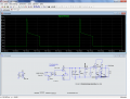
C1, C2, and C5 are all filter caps. M1 is the switch to charge the discharge cap. C2 is the smaller pulse cap, although it is covered up with values. And M2 is the discharge transistor.
The waveform on the top is like a scope trace of the gap voltage. I was trying to show how it is not a straight line across at the working voltage, but rather decays as the cap discharges.
 

ronv

Joined Nov 12, 2008
3,770
That scope trace is about as text book perfect as it is possible to get.
OK, Here we go.
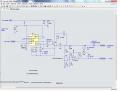
This is the first section. The input signals are on the left and outputs on the right. It charges the pulse cap. It has a FET driver IR2110, a FET switch to turn on and off the 95 volts to the cap, an isolated supply (I'll add a link later), a little 12 volt supply for the logic, a comparator to sense that the cap has reached about 90 volts, the pulse cap (20Ufd.) and the diode going to the spark switch. Take a look and see if it is clear to you.
I thought of another possible problem last night (while asleep). Lets say you have a big pulse cap switched in because you want a long burn, but then set the time short.... The working voltage will measure high causing the probe to move in. I'm worried this could eventually lead to a short. I know we will detect a short, but I think it would be better to avoid it if we can because it will be hard on everything. I have some ideas for this, but maybe you know how it is handled in other machines??
 

Attachments

Thread Starter

shortbus

Joined Sep 30, 2009
10,049
Wow Ron!! You are really helping me, and I feel so inadequate in this. How will I be able to ever repay you? I'll look this over after printing it out.

Usually the gap voltage is read right at the point where the leads go out from the "spark generator" to the electrode and work piece.

But measuring it in the cap bank is one of the things I was planing while I was working on this myself. To be one of the signals for the logic train. If the voltage on the cap bank was not at a certain level it would inhibit the sequence until the set voltage was reached. There would also be another comparator to signal when the voltage dropped below the low window by a certain amount, to shut down the discharge and allow the sequence to start over. By doing this, I was thinking that the discharge timer could be eliminated. Making the discharge time self regulating, bigger cap value chosen - longer on time. With no other input from the operator. Only the off/recharge time to mess with.

Again Ron thank you for all your help!!!
 

ronv

Joined Nov 12, 2008
3,770
Wow Ron!! You are really helping me, and I feel so inadequate in this. How will I be able to ever repay you? I'll look this over after printing it out.
Don't thank me yet. Wait until after your shop has filled up with smoke. :D
Usually the gap voltage is read right at the point where the leads go out from the "spark generator" to the electrode and work piece.
Right - The window comparator.

But measuring it in the cap bank is one of the things I was planing while I was working on this myself. To be one of the signals for the logic train. If the voltage on the cap bank was not at a certain level it would inhibit the sequence until the set voltage was reached.
Ahh, I thought you wanted it for consistency. But without it I thought you could fool the gap voltage.
There would also be another comparator to signal when the voltage dropped below the low window by a certain amount, to shut down the discharge and allow the sequence to start over. By doing this, I was thinking that the discharge timer could be eliminated. Making the discharge time self regulating, bigger cap value chosen - longer on time. With no other input from the operator. Only the off/recharge time to mess with.
Let me think about this one. :rolleyes: Right now, if you did it that way, I'm not sure how you would know if you were to close or to far away from the work piece without calculating an average value for the actual voltage.. It is kind of nice to know the maximum on and off time because that way the time to recharge can also be calculated making sure the power supply caps are big enough and that the transformer rating isn't exceeded. My thinking before this was to only look at the window for a short time in the middle of the pulse length and decide to move in, out or stay the same. Let me sleep on it.

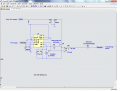
I should have the high voltage pulser tonight - it's almost the same circuit without the cap.
 

ronv

Joined Nov 12, 2008
3,770
OK, now I'm the one with all the questions. :D
This one is about the stepper:
Let's say we are just getting started with burns, so every 400 usec the EDM sends the stepper a move in because the gap voltage is to high - probe to far away from work, but close enough to arc.
The question is will the stepper take 1 step? And if so will it move "in" more than the amount of material burned off in the same time it took it to move? Let's say it takes it 5 ms to do a step that would be another 13 burns. Or do I not understand or does it need or have a PID control?
 
Last edited:

Reloadron

Joined Jan 15, 2015
7,908
Ron, I may be able to help with some of this. While a stepper motor isn't the best choice it can likely work. A servo motor makes for a better choice but anyway. I believe in his case the stepper is driving a lead screw so at least two things need to be known. The number of steps per revolution and if this stepper motor does half steps? Also the lead screw pitch needs known. Typical stepper motors used in applications like this are 1.8° steps or 200 steps per 360° revolution. If the motor and controller can do 1/2 steps then each step is 0.9° and we get 400 steps per revolution. Assuming no gear head on the motor if the motor is driving an acme lead screw with a pitch of 10 TPI (Threads Per Inch) then each revolution of the lead screw is 0.100". At this point we do the math to see what each step or half step converts to in head travel in or out. There is also a need to calculate the head speed based on the frequency of the pulses driving the stepper controller. The stepper controller will control the direction of travel and the frequency it is fed the speed of the travel. I haven't a clue as to what any of that information is for what he has. I have seen some references to the project in other threads.

Also as a side note when measuring the arc voltage across the gap the voltage pickup leads should be as close to the gap as possible. This eliminated I*R loss of the cables between the power supply and torch head. This is a concern when running high current like a few hundred amps, I haven't a clue what the loss will be running lower current but it will depend on the wire gauge to the head.

Back to the motor drive mechanism. Generally a servo motor is used with a 10 turn feedback pot which is gear driven off the head. This is how the head knows where it actually is. Short of counting steps and using a micro-controller I am not sure how to do this with a stepper motor? Doing this with a servo amplifier is relatively easy. You preset the arc voltage you want and the head chases it. Anyway, the steps need worked out and you will need all the data on the stepper motor and motor driver/controller.

Ron
 

MaxHeadRoom

Joined Jul 18, 2013
30,772
The EDM Project Book by Robert Langois uses a Unipolar stepper motor, it is explained in his book which I believe Shortbus has.
Max.
 

Reloadron

Joined Jan 15, 2015
7,908
The EDM Project Book by Robert Langois uses a Unipolar stepper motor, it is explained in his book which I believe Shortbus has.
Max.
That should help. By the way, I really liked the material you posted way back in the thread, there were a few PDFs. My EDM and automated welding machine days ended years ago so I only have memories of the stuff I was sucked into. I know a stepper will work I am just not sure how to make the controlling cartoons. :)

Thanks Max
Ron
 
Top