Hey guys,
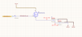
I'm looking for a circuit that generates -5V from a +5V signal from a microcontroller to open and close a depletion mode n channel-mosfet. I figured this could be done with transistors/solid-state devices but I'm stuck and would appreciate some help with this
I'm looking for a circuit with the following input/output/behavior:
Input: +5V --> Output --> -5V --> FET OPEN
Input: 0V --> Output --> 0V --> FET CLOSED