Facebook
 Google
 GitHub
 Linkedin
Hi everyone, I am a first time poster, a CS graduate, and Not an EE but I always attempt to learn. I don't seem to be getting where I want to be with this circuit design and figured I would post what I have and what I am trying to do. Hopefully, someone can provide guidance.
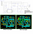
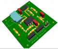
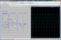
I have a 3 phase system...a split power supply coming off a wall wart; an LC oscillator; and finally the power amplification stage.
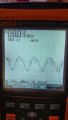
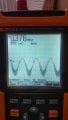
The oscillator phase is currently providing/outputting a steady ~9Vpp at ~300kHz. Looking at the output in the oscilloscope without the power stage and all is good. I get a beautiful sine wave at the required frequency! When adding the power phase things go south. I have added images for my amplification stage with an input that matches the output I see on the implementation of the oscillator phase.
The output in the simulator looks great. But, the output of the implementation is very messy and has an offset on the negative side.
The opamp is a LM6181 and I believe it to be the correct choice.
Let me know if there is something I can provide that would make this clearer/easier to understand. Thanks in advance for your help.
I have a 3 phase system...a split power supply coming off a wall wart; an LC oscillator; and finally the power amplification stage.
The oscillator phase is currently providing/outputting a steady ~9Vpp at ~300kHz. Looking at the output in the oscilloscope without the power stage and all is good. I get a beautiful sine wave at the required frequency! When adding the power phase things go south. I have added images for my amplification stage with an input that matches the output I see on the implementation of the oscillator phase.
The output in the simulator looks great. But, the output of the implementation is very messy and has an offset on the negative side.
The opamp is a LM6181 and I believe it to be the correct choice.
Let me know if there is something I can provide that would make this clearer/easier to understand. Thanks in advance for your help.
Attachments
-
 452.5 KB Views: 23