Negative and Positive Bridge rectifier

Thread Starter

JamesNichols

Joined Oct 8, 2011
4
I'm new in electronics and I'm learning to work with AC and DC.

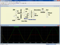
I want to build a bridge rectifier and be able to select the output between negative AC part or positive. I'm posting a picture to explain it better:

When the push switch is pushed the output is positive
When it's not pushed it's negative.

I've no idea how to build the circuit and the diodes I need to use.

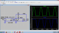
The only way I've thought is the one you can see in the second file attachment. Is correct?
 

Attachments

Last edited:

Wendy

Joined Mar 24, 2008
23,415
You are over complicating this concept. Where you pick ground to be is what defines + or -. Put a switch to move ground on the DC side and there you go.
 

Thread Starter

JamesNichols

Joined Oct 8, 2011
4
You are over complicating this concept. Where you pick ground to be is what defines + or -. Put a switch to move ground on the DC side and there you go.
So you mean that don't touch the AC side and only switch the ground of the dc side. I understand that the only thing I need to do is to change the DC connections from the bridge. If don't touch the original configuration I will get positive, and If I want negative simply I change the connections from + and - to - and +. Right?
 

Georacer

Joined Nov 25, 2009
5,182
Yup, that's what he said. If you want to do it automatically, you might find double rotary switches that will suit you. Be careful not to short-circuit the + and - terminal.
 

SgtWookie

Joined Jul 17, 2007
22,230
In your first schematic you're showing 240VAC coming into a box, and rippled DC coming out; showing a power switch and a DPDT switch.

I most certainly hope that you plan on having a transformer in there somewhere. Working with mains power is quite dangerous. You need to isolate your circuit from the mains power by using a transformer.
 

Thread Starter

JamesNichols

Joined Oct 8, 2011
4
Thank you very much to all

And how is it a half wave bridge rectifier? I'm only interested to get the negative part of the wave in the output
 
Last edited:

MrChips

Joined Oct 2, 2009
30,708
In reality, there is little difference between positive and negative. It is just a matter of where you connect your ground.
 

Adjuster

Joined Dec 26, 2010
2,148
Thank you very much to all

And how is it a half wave bridge rectifier? I'm only interested to get the negative part of the wave in the output
A bridge rectifier is a full wave rectifier. If you are looking to obtain only the negative-going or positive-going half-cycles from the input, then you need to use something different.
 

Thread Starter

JamesNichols

Joined Oct 8, 2011
4
I'm interested in getting this:
http://www.eecs.tufts.edu/~dsculley/tutorial/diodes/halfWaveOut.jpg

Half wave rectification. Well, when I connect the AC input I only want to get the negative pulses without the positive ones. In the last question I asked to get the full wave rectification and connect the wires to get the negative part. Now I want to know how to get only the negative part withouth the positive. Like I show in the picture. The voltage it doesn't matter since in the picture you can read 5 Volts, but I'm not interested in any quantity by now.
 

dataman19

Joined Dec 26, 2009
135
So you want a half wave rectifier... Not a Plus (+) and Minus (-) bridge rectifier output...
Simple...
Use a center tapped transformer..
On one leg put a Diode Rectifier oriented to give a positive voltage.
On the other put a Diode Rectifier oriented to give a negative voltage.
Use the transformer center tap of the secondary winding for the common (ground?).
..
This will give you what you want (a positive and negative half wave rectifier). Using a bridge rectifier with a center tapped transformer secondary will only give you a positive and negative voltage. You are looking for half wave rectifications - which calls for a single diode, not a bridge.
Dave
 
Top