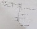
need to spin a small mirror at a specific rpm.. off-the-shelf/simple options?

Thread Starter

robinscottlawrie

Joined Feb 15, 2018
96
the sort of controler your talking about has x/ y mirrors , controled by "galvonometers" , I.e things yo move the laser light in x/ y directions ,
they are doing the synchronised x/ y sweep for you ,
I can't see what this rotating mirror is going to do then !
can you post a sketch of the system please to help
the rotating 45 degree angled mirror provides a 360 degree horizontal sweep (think "cieling fan made out of coloured light") , something that is impossible with galvos, which, at best have 20-30 degrees of movement, and the wider the movement the slower they go.
 

drjohsmith

Joined Dec 13, 2021
1,667
the rotating 45 degree angled mirror provides a 360 degree horizontal sweep (think "cieling fan made out of coloured light") , something that is impossible with galvos, which, at best have 20-30 degrees of movement, and the wider the movement the slower they go.
can you draw us a sketch plesae , from what your saying g the laser control is incompatible with the setup .
 

Thread Starter

robinscottlawrie

Joined Feb 15, 2018
96
the sort of controler your talking about has x/ y mirrors , controled by "galvonometers" , I.e things yo move the laser light in x/ y directions ,
they are doing the synchronised x/ y sweep for you ,
I can't see what this rotating mirror is going to do then !
can you post a sketch of the system please to help
as soon as i have my 3d printer fixed (it died at the worst moment) ill be 3d printing the parts ive prepared so i can rig up a full test and check if the effect is as nice as im hoping. ill upload some images then to give a better idea of my aims.
 

drjohsmith

Joined Dec 13, 2021
1,667
as soon as i have my 3d printer fixed (it died at the worst moment) ill be 3d printing the parts ive prepared so i can rig up a full test and check if the effect is as nice as im hoping. ill upload some images then to give a better idea of my aims.
a hand sketch of the expected setup would be great .
 

Thread Starter

robinscottlawrie

Joined Feb 15, 2018
96
i see no incompatibility. the laser module is self contained, the galvos are a seperate system which i dont need.. worst case scenario i ignore the galvo data in the wave files and use only the channels to control the rgb colours. my aim in this thread is to 1. find a way to set a precise rpm on the mirror , matched to the refresh rate of the laser pattern
2. sync the motor rotation to the laser pattern if possible, either through hardware, controller, or modification of the wave file to provide timing information (i am in contact with the guy who wrote the software that makes the wave files) - he also developed a controller for his own galvo based rgb lasers, so i could potentially get a modified version of his controller if he is willing and/or not too expensive.
 

ronsimpson

Joined Oct 7, 2019
4,856
I have designed too many CRT (monitor) controllers.
One method is to use a Phase Lock Loop to hold the motor at the same speed as the video.
The reverse could work, where you run the motor, at the speed it wants to run at, then change the master clock in the video controller to phase lock to the motor.
Either way I have used CD4046 (MC14046) to "edge lock" video sync to something.
 

drjohsmith

Joined Dec 13, 2021
1,667
fantastic,
so that will just draw a line around the room, no height involved, the colour and brightness involved, controled by the wave file.

I thought you wanted some height , in which case you will need a second synchronised mirror.

anyway, given you want a line out,
assume the laser put out a small spot of light,
when that happens is determined by the pc clock that's driving the laser ,
that has say 0.1 percent variation over time , voltage of psu, temprsture , thats 0.36 of a degree
say the motor is linked to a crystal controler , that speed will be also same error, 0.36 degree
so if your sending g laser 10m from mirror to screen, thats 0.72 degree error is going to wander by what width?
 

ronsimpson

Joined Oct 7, 2019
4,856
In 1983 (+/- a little) I was designing a light valve theater projector. We were throwing 1000s of watts at the wall.
Before that we worked on a laser projector. Much like what we are looking at here, but much bigger. From the center and back of the theater the picture looks good. In the front the picture "sparkled" or "shimmered". It was distracting to watch. I don't remember that lasers were used. Things have probably changed in that many years. Just a word of warning, we could not make one that was acceptable.
 
Apologies if I’m repeating something already suggested, I haven’t followed all the links. I’d use a small dc motor, preferably one with a relatively low RPM rating, and have a vane pass an opto interrupter once per revolution. Use a processor to log the time per revolution which should be 25ms. Use a trim pot to get the speed about right with PWM output into a transistor. Maybe use 10 revolutions to target 250ms, adjusting the speed relatively slowly. An ATtiny85 has 5 i/o pins, so enough to add sync with the laser if desired. A Digispark ATtiny85 would avoid the need for a programmer and it comes with an onboard voltage regulator, if you can live with the 5 seconds delay on start up. A flywheel to add some inertia and reduce cogging would be nice but not essential. A relatively simple speed control algorithm should suffice.
 

drjohsmith

Joined Dec 13, 2021
1,667
In 1983 (+/- a little) I was designing a light valve theater projector. We were throwing 1000s of watts at the wall.
Before that we worked on a laser projector. Much like what we are looking at here, but much bigger. From the center and back of the theater the picture looks good. In the front the picture "sparkled" or "shimmered". It was distracting to watch. I don't remember that lasers were used. Things have probably changed in that many years. Just a word of warning, we could not make one that was acceptable.
laser speccle is real and all but unavoidable
the surface the laser hits is not flat at the frequency of the laser , so the spot hits many different heights, so the light reflected is at varying phase to the light being sent, and adjacent waves. the eye does a summation of the different waves, creating fennel fringes .. constructive and destructive , bright dark light.
https://en.m.wikipedia.org/wiki/Speckle_(interference)
 

Thread Starter

robinscottlawrie

Joined Feb 15, 2018
96
@robinscottlawrie

How's it going ,
can I check it is this line you are wanting , not a x / y display ?
exactly, its a simple 360 degree horizontal fan. rather like a laser level, although those dont use a spinning mirror (they use a diffraction grating and a conical mirror. an easy solution, but impossible to vary the colour around the "disc" as its all projected simultaneously).

to be more specific the beam actually terminates on a thin ring of translucent white plastic about 1.5m in diameter, which, in my testing glows on both sides very pleasingly when hit by a 3 watt beam. there is also an inbuilt fogger in the device that makes the entire disc of light quite visible. obviously motor feedback is essential since if the beam stops spinning it would burn through the plastic ring in a couple of seconds.
 

Thread Starter

robinscottlawrie

Joined Feb 15, 2018
96
another thought i had, just putting it out there, is that instead of having motor feedback, i could have a few small photosensors spaced around the ring. if they dont register a pulse within a second (for example) it all shuts down.

compared to a motor encoder this would also protect against the ring getting damaged, knocked out of alignment, or likewise the laser or mirror shifting somehow.

i really need to consider these things (plus a few more layers of protection) if the project goes forwards, as, if my "client" likes the thing it would be installed (high up) in a public place and multi watt lasers are no joke.
 

drjohsmith

Joined Dec 13, 2021
1,667
exactly, its a simple 360 degree horizontal fan. rather like a laser level, although those dont use a spinning mirror (they use a diffraction grating and a conical mirror. an easy solution, but impossible to vary the colour around the "disc" as its all projected simultaneously).

to be more specific the beam actually terminates on a thin ring of translucent white plastic about 1.5m in diameter, which, in my testing glows on both sides very pleasingly when hit by a 3 watt beam. there is also an inbuilt fogger in the device that makes the entire disc of light quite visible. obviously motor feedback is essential since if the beam stops spinning it would burn through the plastic ring in a couple of seconds.
what sort of eye safety / human safety features are you building in ? great your asking, but a few ns is enough to burn out an eye , depending on the laser . if its

IMHO,

if you can its much easier to lock the sw to the motor speed ,
but you need to check with your sw provider by the sound of it .
 
Regarding the feedback portion, which seems to be your main concern and why you started this thread:

You may want to look into how the Neato Robotics XV11 Lidar system works; this has been well documented.

After looking, the original source and hack and such - well, most of that has either disappeared, or may be buried somewhere in github; I'm not sure.

But basically, in 2011 or thereabouts, there was a challenge to "hack" the XV11's Lidar unit, so it could be used in hobbyist/DIY/research robotics; someone claimed it rather quickly, and today, the equivalent code is now available within ROS (Robot Operating System), and probably isn't much used any longer, because more effective and just as cheap Lidar sensors and such now exist.

But code of a similar nature (and simpler than digging thru ROS) can still be found; for instance:

https://svenssonjoel.github.io/pages/neato_lidar_stm32/index.html

You probably want to focus on this section (which someone else posted about how you would implement a similar scheme earlier in the AAC thread); look for the sentence "The calibration routine performs a so-called binary search over the PWM duty cycles and tries to lock down on a duty cycle that results in 300RPM." - it's about 1/3 of the way down, and code is shown.

Basically, what the sensor did, once spun fast enough (approx 5 rpm), was spit out data from the sensor, of which the main concern was RPM - so it dumped out the RPM value, and then it was read, then averaged (over time), and the PWM to the motor (which is just a cheap DC motor like you're working with) is adjusted to keep the RPM value to about 300 RPM.

That's important for the Lidar unit, because then it spits out in the serial data stream the distance readings from the Lidar - which is what is wanted.

So - all you would need to do is to use a similar routine to instead of adjusting the RPM value to 300 RPM (note - in the code, it is shown as "60000" - because the code reads the RPM value 200 times, and then looks for it to be close to "300 RPM" - 60000/200 = 300).

So, if you did something similar, you would use 2400 * 200 - ie, 480000 - as your number (you can adjust the number of samples up or down from 200, of course - just change the count accordingly).

All you need to do then, in order to use something like this - is get the RPM. Fortunately, you have a spinning laser. And every time it goes by, that's a signal you can use. Count the number of flashes in say, 1/4 second, multiply that by 240 - ie, 60*4 - and that's the motor's RPM.

Then use that value directly (no real need to do the for-next loop for 200 times as the XV11 code does it - that's what is done above when you count the flashes); check that value for higher or lower, then adjust the PWM output to raise or lower the speed of the motor until the target RPM is reached.

How to get the flashes - ah, there's the rub, because you don't want to "shadow" the laser you're generating; in the Neato lidar, it likely uses a photo-interrupter on the shaft of the lidar unit itself (it's driven by a belt from the motor) - so it's actually measuring the RPM of the Lidar (laser) platform - not directly of the motor (which is basically what you need, since it's direct-driven).

You just need a bit of the light - and I would bet (you'll need to experiment) that some of that light that exits the glass tube, is reflected internally. So - if you position your flash sensor (just a simple photo-transistor would work fine) just below (maybe level with the motor's case where it's shaft exits, and maybe "baffle" it so that it just picks up the light as is sweeps near/over the sensor - you don't want anything from say, the other 359 degrees; this will need experimentation) - you should be able to pick of the flash, and from there, get your RPM as described above.

I hope this helps in some manner - again, your only real issue is getting that RPM output.

Oh - another possibility - depending on the room you have to work in:

If you can make the mirror holder a bit wider than the case of the motor, then you could place below it an opto-reflective sensor; a common and small one is the RPR220, another is the TCRT5000 - you can get a small handful for a few dollars, and there is a ton of code out there about using them with a microcontroller/arduino. You can even buy small "modules" that you can use with an arduino (which I would suggest - just cut the sensor off, and mount it remotely to the board - so the sensor part is small enough to fit in your space).

There are tons of options for these reflective sensors - and if you look, you can find some that are about the size of a pencil eraser. They just have a phototransistor, and an IR LED that shines light - both point in the same direction - so when something reflective passes by the sensor, the phototransistor is "turned on" and you can detect that. The point of using a module, is because the output of the phototransistor is small, and you need to amplify it - the module has all of the amplification circuitry, which isn't complex, but may be more than you want to deal with (and debug) - but you can also find amplification schematics and/or the schematics for those modules if you look for 'em.

So - with it pointing "up" toward the underside of your spinning reflector - if you put, say, a small white dot on it (or a black dot - whatever your color of the reflector part is, it's need to contrast sharply with a small portion of opposite contrast for your "pulse" output - if you could mount a small IR reflective mirror on the underside, it would be perfect, but don't ask me where you'd get an IR reflective mirror that small; easier to just say, paint the underside black, and put a white spot on it somewhere).

If you can do that - bam, there you go - that's all you should need. I hope this helps you.

Good luck!
 

lichurbagan

Joined Jul 4, 2025
137
Hi all, One of my many small light/art projects requires an angled mirror to spin at precisely (or as near as possible) to 2400 rpm. being a small (1cm diameter) circular mirror, on a tiny 3d printed holder, the load on the motor is minimal.

the motor itself can be anything as long as its small.

the speed needs to be as close to precise as possible since it needs to (approximately) sync with a laser which repeats a pattern 40 times a second. if its a bit off, the pattern will slip a little. thats fine (its an art piece after all) . however if its way off the pattern wont work at all.

another alternative would be to read the rpm from the motor and sync the laser to that... probably better but ive no idea if its doable- the laser is driven by a multichannel wav file through a dac. . another thing to research. trying to decide what the best approach would be.

this is one very small part of quite a complex project, plus my skills are not exactly "genius level" so i need a solution that isnt too complex.

i had assumed that some pre-made sketch for arduino would be available, using a small motor with rotary encoder, but from what i have read, its actually not so simple, and there does not appear to be anything off-the-shelf i can load onto an arduino and hit go. given thats about the level of my arduino skills.... hmm.

so im wondering if there is a relative simple circuit that can achieve this goal, or, even better, some ready made small motor/fan speed controller that can be utilised. i did look into synchronous motors, generating an ac waveform at the chosen frequency should not be beyond my skills.,.. however all the ones i found for sale are a single block with inbuilt gearbox (very low rpm) or great big things to drive large loads. i also looked into stepper motors, but driving them to 2400rpm is apparently also quite complex, depends on the motor chosen, you need to ramp the speeds to avoid missing steps, and the controller needs to handle quite fast switching.

any tips on the most straightforward solution most appreciated.
You can use a small 5 V fan with a tachometer output as a precision motor for your mirror by first mounting your 1 cm mirror onto the fan shaft or a tiny 3D-printed hub that fits securely. Ideally, remove the fan blades to reduce imbalance and vibration. Make sure the mirror is centered and balanced; even small wobbles at 2400 RPM (~40 Hz) could affect the projected laser pattern. Since your load is minimal, the fan’s motor can easily handle spinning the mirror at the required speed.
 
Top