Need to identify an electronic element

Thread Starter

cstroh

Joined Jan 16, 2019
111
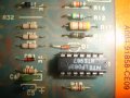
I am trying to repair a circuit board for the alternator on a stationary bike and find a two lead component that I cannot identify. It is about the size of a small diode but has a clear glass like covering with no diode like markings or identifiers. It is between the main voltage source and the negative input on an operational amplifier. The part is maybe 1/8 inch long and maybe 1/16 inch in diameter. Any ideas?
 

Reloadron

Joined Jan 15, 2015
7,889
A good quality sharp image would be nice? It could be most anything. Also as we have many members globally you would do better to give dimensions as L = 0.125" (3.175mm) D = 0.0625" (1.5875mm). You are saying it is between the inverting input of an op-amp and VCC? Do you know what the circuit actually does? That would help too.

Ron
 

Thread Starter

cstroh

Joined Jan 16, 2019
111
A good quality sharp image would be nice? It could be most anything. Also as we have many members globally you would do better to give dimensions as L = 0.125" (3.175mm) D = 0.0625" (1.5875mm). You are saying it is between the inverting input of an op-amp and VCC? Do you know what the circuit actually does? That would help too.

Ron
The item of interest is labeled D1 in the attached picture. As best I can tell. the power from the alternator is initially powered by a 9 volt battery to the field of the alternator while you activate the alternator by pedaling. The subject element feeds back what voltage the alternator supplies to the V- side of a differential operator. The Vout from that differential operator replaces the power to the alternator field when the 9 volt battery is removed. The dimensions are as you stated above L=0.125" (3.175mm) and D=0.0625" (1.5875mm). Hope this helps.
 

Attachments

iONic

Joined Nov 16, 2007
1,662
Wow. pretty interesting. typically the like D1, R12, C3 represent parts like Diode 1, Resistor 12, Capacitor 3. It looks like a diode but there is no markings on it do designate the cathode and anode. Oddly, the symbol under D1 does not suggest diode either. Oddly, again, the symbol under the number CB1 is a diode symbol and the part is definitely a diode, a 41xx. So I am stumped as well here.
 

Thread Starter

cstroh

Joined Jan 16, 2019
111
That's a poor top-silk layer. Anyways, it looks like a diac to me.
I thought for sure it would turn out to be a diac so I disconnected one lead and did a diode check with a Fluke multimeter in both directions. It showed open in both directions and a resistance check gave the same result. Any more ideas?
 

Thread Starter

cstroh

Joined Jan 16, 2019
111
Attached are involved circuits. The first one with an F listed is part of the circuit for the field voltage to the alternator. The second circuit shows input to a 4 stage Operation Amplifier referred to as Z1. The unidentified element is in the middle of the page and labeled D1. The problem I am having is it takes multiple starts before launching into the program. Once in a program and run to the end. A restart is immediate. So something is benefiting from running the program. Do not know what D1 does or if it is defective as both diode check and resistance check gives open circuit. If anyone can figure out what is going on and if D1 is involved it would be appreciated.Field Circuit.JPG Operational.JPG
 

DickCappels

Joined Aug 21, 2008
10,661
If it is a diac or transient voltage protection device it would appear open with less than several volts. For diacs this voltage is likely to be in the range of 25 to 40 volts.

Edit: Corrected cell phone induced typos.
 
Last edited:

MisterBill2

Joined Jan 23, 2018
27,513
My guess is that it is a Zener diode and that it may have been too hot for a while. There have been a number od different diode types in that same 2-lead TO92 package. Not a diac, because why would that be in a DC assembly??
 
I have several identical looking components. I have them marked as 1n914s and they meter as I would expect of a silicon diode .5v/over. Mine are, however, quite old.

IMG_8919cR.jpg
 

Thread Starter

cstroh

Joined Jan 16, 2019
111
My guess is that it is a Zener diode and that it may have been too hot for a while. There have been a number od different diode types in that same 2-lead TO92 package. Not a diac, because why would that be in a DC assembly??
Does a Zener diode act like any other diode in the forward direction? I get nothing with a diode check in either direction. On the circuit board the designation for a Zener diode appears to be ZCR with a diode picture underneath the element, for this element only D1 with something like a half circle picture underneath?
 
Last edited:

MisterBill2

Joined Jan 23, 2018
27,513
I have an FM car radio tuner board that has three voltage variable varicap diodes that look exactly like the graphic under that device. But that makes no sense for an alternator control board. No sense at all.
So probably what will make a repair possible is to come up with a circuit of the system and also to define the problem in detail. At that point it should be possible to determine what parts are not functioning correctly.
Is that device the only component connected to the opamp inverting input? or the negative supply terminal of the IC?

AND, what is the specific complaint about how the stationary bike performance? That may be a very useful clue.
 

Thread Starter

cstroh

Joined Jan 16, 2019
111
The bike uses a 9 volt transistor battery for startup, you pedal up to maybe 80 rpm and push a switch to momentarily tie in the 9 volt battery. On a cold start, it may take 2 to 3 attempts to start, each time requiring bringing the bike to rest. During these failed startups, I get differing reactions. On one, all the lights on the display board may flash. On another I get no lights but pedaling force increases noticeably. On the third attempt, everything works normally. If I go thru the complete program the bike as expected shuts down at the end. After going through a whole program and shut down, a single re-start will be successful. As if something is depleted with time but once charged is good. Replaced most capacitors with no success.
 
Does a Zener diode act like any other diode in the forward direction? I get nothing with a diode check in either direction. On the circuit board the designation for a Zener diode appears to be ZCR with a diode picture underneath the element, for this element only D1 with something like a half circle picture underneath?
I don't get that at all. Can someone explain better at least what is usually done? The silk screen uses CR for diode, I can see that and that is usual in my limited experience. The silk screen also uses D for something (what we are trying to determine). I have certainly seen CR or D used for diode, but both on the same silk screen?? ...and that symbol...I have only seen something like that in reference to an LED but the orientation is wrong (relative to the board holes). Is there a CR1 AND a D1 on the silk screen? Is there anything on the silk screen being covered by the component?
 

Thread Starter

cstroh

Joined Jan 16, 2019
111
The shape of the silk screen under the unknown element is the same shape they used for several small transistors with 3 leads. Maybe the shape is not significant and just happened to be what they had on hand. As previously mentioned, a diode check in either direction as well as a resistance check in either direction on the unknown element shows OL in all cases. So either the element has failed or it will only react to a higher voltage then is applied in the diode or resistance check.
 
The shape of the silk screen under the unknown element is the same shape they used for several small transistors with 3 leads. Maybe the shape is not significant and just happened to be what they had on hand. As previously mentioned, a diode check in either direction as well as a resistance check in either direction on the unknown element shows OL in all cases. So either the element has failed or it will only react to a higher voltage then is applied in the diode or resistance check.
Is it totally crazy to use a transistor junction as a diode? I remember doing that for white noise and I read here that it is not uncommon. Is it that a possible reason for the symbol? I could believe that quicker than I could believe that it was just what they had on hand.

This is a better mystery than Oak Island :)

Edited to add: To be a little clearer, here is my speculation....

When the board was designed, the intention was to use two leads from a three lead transistor as a diode. Whether this was for economic or performance reasons is for you real engineers to determine.

The symbol of a transistor, including orientation was correctly chosen by the designers. That is, it was chosen with intent. That is why it is NOT consistent with the CR designation elsewhere on the board and why they instead, used the D designation, even though the component was intended to be a transistor, but used as as a diode.

At some point, they decide to use a silicon diode as a replacement/substitution for the transistor. Again, whether this was for economical or performance reasons is beyond my skill level.

This speculation is supported by (not definitively) the components that I illustrated and that look identical to the one on your board, but are absolutely diodes and with a voltage drop consistent with common silicon diodes.

So, figure out the correct orientation and use a 914 - and if it all goes up in smoke....I was definitely wrong. :)
 
Last edited:

Thread Starter

cstroh

Joined Jan 16, 2019
111
Are you suggesting that this is essentially like a Zener diode and if so why did they not use a plain Zener diode?
 
Top