 Facebook
 Google
 GitHub
 Linkedin
Hi, everyone! I'm the new here, and I just started to get involved in circuit design. I need some advice for my project. The first picture is a picture file of my circuit design. There are two RCL filers in this circuit, and one filter is for changing square wave to sine wave and the other one is for changing sine wave back to square wave.
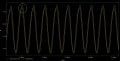
Now, the second picture is a diagram generated by Pspice. My problem is that anyone knows how to make the green line and red line have bigger variance at the high peak. I was trying to adjust the value of R, C, and L, but it just showed a mess. Please let me know any advice and I will be appreciated. Thank you!
Now, the second picture is a diagram generated by Pspice. My problem is that anyone knows how to make the green line and red line have bigger variance at the high peak. I was trying to adjust the value of R, C, and L, but it just showed a mess. Please let me know any advice and I will be appreciated. Thank you!
Attachments
-
 22.1 KB Views: 23
 -
 48.7 KB Views: 17


