Need some help with Switches/Buttons and mA specs

dl324

Joined Mar 30, 2015
18,427
I should definitely have enough room on the board for a timer. Just so happens I have some 555 timers.
What on time do you want?
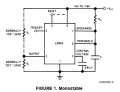
From National Semiconductor datasheet:
1648176400861.png
On time is 1.1RaC.
BTW that MOSFET chip was super tiny. Soldering wasn't a problem but seeing the chip was another story.
Small, but inexpensive. Did you mount it on a SMT to SIP adapter?

For a dime (in quantity 100), you can get 2N7000, but they only have 1/20 of the current capability and have a higher threshold voltage.
 

MisterBill2

Joined Jan 23, 2018
27,809
Thanks for the followup. I put a 1M ohm resistor across(parallel) the capacitor and it did discharge the capacitor in approximately 3min 45sec. It slowly dimmed the LED until it was fully discharged. Is there a faster way to go from the on/off transition so I go from full voltage to nothing?
A schmidt trigger device as a driver, in between the cap and the mosfet gate would change states quickly at some point. no extra components will be needed except for the aditonal 14 pin IC. Certainly a 555 timer IC will work but it will need a few external parts.
Given that this is a toy type of device is there really a problem with the LEDs dimming to off? It might even become a sort of game.
 

BobTPH

Joined Jun 5, 2013
11,580
Thanks for the followup. I put a 1M ohm resistor across(parallel) the capacitor and it did discharge the capacitor in approximately 3min 45sec. It slowly dimmed the LED until it was fully discharged. Is there a faster way to go from the on/off transition so I go from full voltage to nothing?
Yes, get rid of the capacitor.

I don’t understand what you are trying to do. You have a momentary push button. Do you want you toy to operate only while the button is held down, or for some time after the button is released? Toggling on / off is also an option. Which are you trying to do?

Bob
 

MisterBill2

Joined Jan 23, 2018
27,809
Yes, get rid of the capacitor.

I don’t understand what you are trying to do. You have a momentary push button. Do you want you toy to operate only while the button is held down, or for some time after the button is released? Toggling on / off is also an option. Which are you trying to do?

Bob
First there was a comment about leaving the box on running the battery down. So then a 555 timer was suggested. Then I explained that as the power control was a mosfet all ready, a simple capacitor could be charged to switch the power on for a while.
What is unclear to me is why a dimming switch-off is not OK. It worked very well with a toggle switch but that did not provide any eventual turn off .
 

Thread Starter

Happ

Joined Mar 18, 2022
22
What on time do you want?
From National Semiconductor datasheet:
View attachment 263541
On time is 1.1RaC.
Small, but inexpensive. Did you mount it on a SMT to SIP adapter?

For a dime (in quantity 100), you can get 2N7000, but they only have 1/20 of the current capability and have a higher threshold voltage.
I used the SMD SOT23-3 to DIP SIP3 adapter to mount the chip on. The time on I was looking for was 2 min. 45 sec.
 

Thread Starter

Happ

Joined Mar 18, 2022
22
A schmidt trigger device as a driver, in between the cap and the mosfet gate would change states quickly at some point. no extra components will be needed except for the aditonal 14 pin IC. Certainly a 555 timer IC will work but it will need a few external parts.
Given that this is a toy type of device is there really a problem with the LEDs dimming to off? It might even become a sort of game.
Normally I wouldn't mind the lights dimming but it has an audio component that would probably start sounding pretty weird with the power gradually dropping off. Great ideas though, I'm learning a lot from everyone here. Thank you all.
 

Thread Starter

Happ

Joined Mar 18, 2022
22
Everyone here has been such a great help. You wouldn't believe how far along I've got this thanks to this group. My project probably seems a bit chaotic because it is. This is a learning process for me so I'm changing things when someone suggests something that sounds like a fun idea to learn and implement.

Here's a summary of what I'm trying to accomplish. At first I just wanted a small button that could handle more than 50mA. A small button because it needed to be inside a small toy that when a key was inserted into the keyhole it would push the button to turn everything on. So a toggle/rocker switch or similar switches probably wouldn't work so well. The MOSFET was then suggested to handle to current which works brilliantly. Then a timed delay was suggested to shutoff the toy after a certain amount of time which I thought was a great idea since it would have to be turned off after the audio finished anyway.

Everyone is giving me great suggestions for exactly what I need but since I'm new to all of this I don't know how they work until I try them. So things evolve as I figure them out like using a capacitor and resistor to turn off everything. Works good but would probably mess with the audio portion as it winds down. So now we're looking at alternatives.

I will make 100 changes if need be for as long as you folks are willing to help. Every single suggestion is appreciated and I'm having fun learning all of this. There are no bad ideas here. So if someone's confused as to why something was suggested it's because of my chaotic project that keeps evolving.

Thank you all.
 

dl324

Joined Mar 30, 2015
18,427
The time on I was looking for was 2 min. 45 sec.
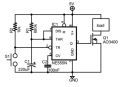
That's a bit long for a bipolar 555 timer, but this might work:
1648222509553.png
The cap tolerance and leakage will likely require you to tweak the value of R1. If you can't get 165 seconds, you can use a larger timing capacitor and smaller R1 to increase charging current to offset leakage.

EDIT: Or use a smaller R1 with the 100uF timing capacitor.

If the SMT to SIP adapter you used has the pulldown resistor on the gate, you can leave it in place.
 
Last edited:

Thread Starter

Happ

Joined Mar 18, 2022
22
That's a bit long for a bipolar 555 timer, but this might work:
View attachment 263582
The cap tolerance and leakage will likely require you to tweak the value of R1. If you can't get 165 seconds, you can use a larger timing capacitor and smaller R1 to increase charging current to offset leakage.

EDIT: Or use a smaller R1 with the 100uF timing capacitor.

If the SMT to SIP adapter you used has the pulldown resistor on the gate, you can leave it in place.
I think that I can follow your circuit but the timer looks different than the one I have which is a Texas Instruments NE555P IC single precision time. It has pins 1-4 on one side and 5-8 on the other. 8 7 6 5
_______
1 2 3 4
 

MisterBill2

Joined Jan 23, 2018
27,809
I suggest giving it a TRY and seeing or hearing what the audio module does as the supply voltage drops. It may just get weaker and then stop, as the digital portion needs some minimum voltage to work, below that it just stops, like a battery running down.
 

dl324

Joined Mar 30, 2015
18,427
I think that I can follow your circuit but the timer looks different than the one I have which is a Texas Instruments NE555P IC single precision time.
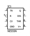
You should get used to using symbols that are designed to convey functionality instead of using pin order symbols, which will rarely be useful in understanding what a circuit is intended to do.

The symbol I use is one I customized. The default symbol used in the schematic editor I use (Eagle) is brain dead.
1648229319822.png
Why it's brain dead. The reset pin is usually connected to V+, so it would make sense to make that easy to do. The CV pin is usually bypassed to ground, so it would make sense to make that easy. Trigger and threshold are connected for an astable, so it would make sense to put those pins close to each other. The preferred flow in a schematic is left to right and top to bottom. Neither the symbol above or the pin order diagram you're familiar with facilitate that.

I don't recall seeing any pin-order symbols for 555 timers indicate that reset is a low active function. At least Eagle got that right.

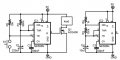
EDIT: Examples of one shot and astable with my symbol:
1648230448102.png
 
Last edited:

BobTPH

Joined Jun 5, 2013
11,580
A small button because it needed to be inside a small toy that when a key was inserted into the keyhole it would push the button to turn everything on.
Too bad you didn’t tell us that at the beginning. A microswitch is what you use for that.

Bob
 

Thread Starter

Happ

Joined Mar 18, 2022
22
I suggest giving it a TRY and seeing or hearing what the audio module does as the supply voltage drops. It may just get weaker and then stop, as the digital portion needs some minimum voltage to work, below that it just stops, like a battery running down.
I went ahead and gave it a shot with the capacitor and resistor. It really messed with the audio if it ran low but I managed to get a resistor combo that got it pretty close to the time I needed without any audio issues.

Now that I know that I can get it to do what I need I'm going to try and setup the circuit with the timer from the other schematic that dl324 provided. Toys break so I figured I'll just make two and put one circuit version in one and the other in the other toy.

Now that you all have helped me work out this project I figure it's about time I grab a book and learn how this stuff is suppose to work and how circuits are intended to work. Thank you so much for everything folks. I'm sure that I'll be getting in over my head with some other projects down the road so I'm sure you'll be hearing from me. Take care everyone.
 

dl324

Joined Mar 30, 2015
18,427
I'm going to try and setup the circuit with the timer from the other schematic that dl324 provided
With the component values used, the nominal timing period would be:
\( T = 1.1RC = 1.1 * 680k\Omega * 100uF = 164.6s \)

Leakage on the electrolytic cap will likely be an issue and may require using a resistor smaller than the formula indicates.
 
Top