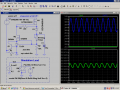
Below is the LTspice simulation of Bordodynov's basic circuit using a TL431 as the regulator control, modified with some added components for proper bias and frequency compensation, and a current limiter.
I didn't have the model for the IRF840 so I used an alternate, but the circuit should work essentially the same with the 840.
Q1 turns on to starve the gate voltage to M1 and limit the current when the voltage drop across R4 reaches about 700mV.
The current is limited to about 220mA, as can be seen after 5ms when the output is shorted by S1.
The output is shown for minimum, midrange, and maximum position of pot U2 for a 200mA load.
Note that the power dissipated in transistor M1 can get quite high at low output voltages and a 200mA load or a short so you would need a healthy heat-sink for operation under those conditions.
Note that I replaced the scheme.
Now I am applying input 310Volt and output is 305 volts.The value of the reference voltage equal to 2.5volts.
Equivalent:
Below is the LTspice simulation of Bordodynov's basic circuit using a TL431 as the regulator control, modified with some added components for proper bias and frequency compensation, and a current limiter.
I didn't have the model for the IRF840 so I used an alternate, but the circuit should work essentially the same with the 840.
Q1 turns on to starve the gate voltage to M1 and limit the current when the voltage drop across R4 reaches about 700mV.
The current is limited to about 220mA, as can be seen after 5ms when the output is shorted by S1.
The output is shown for minimum, midrange, and maximum position of pot U2 for a 200mA load.
Note that the power dissipated in transistor M1 can get quite high at low output voltages and a 200mA load or a short so you would need a healthy heat-sink for operation under those conditions.
What about paralleling 2 IRF840s for M1 to share heat dissipation for low voltage hi current situation?
Also, if M1 failed for some reason during a dead short (Low voltage Hi current) across the output of the circuit, would that not render the current limiting useless?
Is there a way to implement current limiting that does not rely on the pass IRF840 being being functional?
....................
You can parallel two MOSFETs to distribute the heat but you still have the same total amount of heat to dissipate so it doesn't affect the heat sink requirements.
You could add another MOSFET with the NPN transistor limit circuit, in series with the control MOSFET with its own limit.
That would give two (redundant) limits. But then you would likely also need to add some additional circuitry to warn if one of the limits failed. Otherwise you wouldn't know.
crutschow, You ignored my remark on your electronic circuit. Maybe it's my fault and I'm not very detailed description of my experiment with your circuit. I'm sorry. Your electronic circuit is very bad. I knew it was worse than mine, but not enough. This is the advantage of using transistors with built-in channel. The input ripple amplitude I asked 15 volts and a frequency of 100 Hz (SINE(300 15V 100 1m)). Your electronic circuit output voltage ripple gave 7 volts, and my 0.0005 volts. I would like to hear comments.
crutschow, You ignored my remark on your electronic circuit. Maybe it's my fault and I'm not very detailed description of my experiment with your circuit. I'm sorry. Your electronic circuit is very bad. I knew it was worse than mine, but not enough. This is the advantage of using transistors with built-in channel. The input ripple amplitude I asked 15 volts and a frequency of 100 Hz (SINE(300 15V 100 1m)). Your electronic circuit output voltage ripple gave 7 volts, and my 0.0005 volts. I would like to hear comments.
I took your circuit that you have attached (TL431 HV Regulator.asc), and decided to investigate the suppression of fluctuations of the bridge rectifier. Simply show a picture. Look
G.Beard.
ILoad=0.2 Crutschow
The ripple rejection (Cg=1uF, C2=1nF) Kr=30V/0.557V=54. My new cirquit (+10nF) Kr=30V/0.000172V=174418.
Congratulations! You have created a disposable stabilizer. The second time the regulator will not start. But it's easy to fix. Also no-load voltage and full load differ by 4 volts. I have done other studies (comparison) our regulators.
I later add a file to my research of my and your stabilizer.
By all accounts, my stabilizer greatly exceeds yours. But your stabilizer consists of the common components. But if you want to get a high quality stabilizer, use my electronic circuit. The truth is it will be much more expensive.
So, would we then reference the adj pin to a fixed rail x amount more positive WRT ground or use resistor between adj and 0v to elevate the output to a desired voltage, or inject a voltage to the adj pin?
How would one adjust the output over a range greater than 48V? Could this be done maybe by having a pre-regulated variable voltage and..... not sure of the correct terminology... float the LM317 on the varied output of the adjustable voltage?
How would one connect an LM317 (at high voltages) to a circuit without the 48V rating being exceeded?
What voltage is the zener diode?
I can see you are using depletion mode MOSFETs so I should think that when the circuit is initially powered the M1 is fully on, R1 and R2 make up a voltage divider and R4 or R1 set the current flowing through the zener which provides a reference voltage which then raises the gate voltage to M1 and the circuit would stabilise at 120V. I this correct? Would you give a brief explanation of your schematic and correct me where needed please?
Here is a NON-regulated circuit from rod elliott's site that I modified slightly for higher current and lower ripple.
The zener does no appear to be conduction in the zener breakdown region, the zener device was not specified, nor was there any explanation as to what this zener is doing in the circuit. Any input would be greatly appreciated.
The circuit is a transformerless power supply which is not allowed and violated with the TOS, if you continuing to discuss this kind of circuit then the thread will be closed.
 Facebook
 Google
 GitHub
 Linkedin