Need help with two issues with my 50kg load cell

Thread Starter

GarrettVD

Joined Apr 13, 2013
10
Hi,

I recently picked up a loadcell from SparkFun; it has a 50kg capacity. (specifications here: https://www.sparkfun.com/datasheets/Sensors/loadsensor.pdf). When it arrived, I noticed that it only had 3 wires: red, white, and black. I believe it might be in a half whetstone bridge configuration. Not what I expected, but I'll have to make due for now.

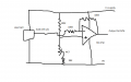
In any case, I connected the White wire to a 6.54VDC power source, the Black wire to GND, and the Red wire is what I was intending to connect to the V+ and V- of my LM358N instrumentation amplifier (a diagram of which can be seen here).

I noticed that if I connect the + of my voltmeter to the Red wire, I get a reading of 3.269VDC. Applying pressure to the load cell with a pair of pliers will result in a 2mV drop, so 3.267VDC. Upon releasing the pressure, it will return to the b3.269VDC baseline.

A few questions:
Should I not just be seeing a value of between 0mv and 2mV coming out of the load cell?
(related to #1) If the 3.269VDC output is not correct, how do I correct this behavior to attain the expected result range?
How should I connect this half-whetstone bridge load cell to my LM358N? (a diagram or a detailed explanation would be very helpful!)

Thanks all, I am new to the whole circuitry thing, but I am a quick learner. :)
 

geoffers

Joined Oct 25, 2010
475
Hi,
I got one of those a while back, wasn't quite what I expected either! Your quite right it is half a wheatstone bridge.
The best option in my opinion is to make the other half! There's a few ways of doing it, the best is to buy another load sensor and use it to make the other side of the bridge, that way you automaticaly get temprrature compensation, the other way which isn't quite so accurate is to use fixed resistors to make the other half of the bridge, you then end up using the black and white wires as the input to your amp, the red wire becomes gnd or +ve depending on which way up you build it. You should then get the sort of output you were expecting. You might want to go through your resistors to get one close to the right value (5% tolarance gives some variation) or I suppose you could use a trimmer/2 trimmers?

Bridge.gif

Hope that makes sense, Geoff

Ps the values on the resistors mean nothing, thats default on my schematic thingy!
 

Dodgydave

Joined Jun 22, 2012
11,285
You need to build an offset amp first like this one, set the pot to give zero voltage at the output of the op amp with no load applied.

As you apply pressure the load cell will give a voltage out, in this circuit the voltage will rise by the same amount on the load cell.

Use high tolerance resistors like 1% for stability.
 

Attachments

Thread Starter

GarrettVD

Joined Apr 13, 2013
10
Quick question for you, @dodgydave. Was curious what the setup with the 4K7 and 98K resistors accomplishes? And also, are these hooked up in series? Not familar with the diagram symbol there.

Cheers!
 

Dodgydave

Joined Jun 22, 2012
11,285
Quick question for you, @dodgydave. Was curious what the setup with the 4K7 and 98K resistors accomplishes? And also, are these hooked up in series? Not familar with the diagram symbol there.

Cheers!
Yes they're in series, its to try and get a close match for the 100K , also to vary the offset through zero volts and compensate for thermal drift.

ps what is the model number of the load sensor?
 
Last edited:

paulktreg

Joined Jun 2, 2008
833
Another question.

Shouldn't you be connecting your power supply to the red and black wires and taking the signal from the white wire?
 

Thread Starter

GarrettVD

Joined Apr 13, 2013
10
Yes they're in series, its to try and get a close match for the 100K , also to vary the offset through zero volts and compensate for thermal drift.

ps what is the model number of the load sensor?
Cheers Dave, thanks again for the help. Unfortunately, SparkFun is a bit skimp in regards to any useful schematics or specific model numbers, but they do provide this specifications document.

Also, after looking at the specifications again, I noticed that the input/output resistence is 1KΩ, which leads me to believe I could use 1KΩ to "fake" a full bridge, instead of 100KΩ?

In any case, I've ordered another load cell to compensate for the other half of the bridge. I'll feed both cell outputs into the instrumentation amplifier I have: one wire into VIn+ and one into VIn-; this should reverse the polarity so as to not cancel each other out. (from what I've read, anyhow). From there, I'll feed the Instrumentation Amplifier's analog output into an MCP3002 ADC chip, and read it into my Raspberry Pi's SPI.

After all of this, I can safely say I have a much greater appreciation for the craftsmanship of my cheap Taylor digital scale. :D

Cheers,

-G.
 

Thread Starter

GarrettVD

Joined Apr 13, 2013
10
Another question.

Shouldn't you be connecting your power supply to the red and black wires and taking the signal from the white wire?
Due to the lack of schematic, I've had to play around with the wires. From what I gather from the comments on the SparkFun product listing page for the load cell, white=V+, black=GND and red=output of load cell. Wish there was some universally accepted standard for all load cells. One can dream!
 

cccimin

Joined Dec 12, 2013
4
Hi, what is the maximum capacity of the 2 load cells in your new circuit? I have the same connections as you. The website says one load cell capacity is 40-50kg, so 2 load cells in this circuit should be able to take max. 100kg load?
Im a bit confused because i couldnt get more than 40kg with 2 load cells. Were you able to get 100kg max with 2 load cells?
 
Top