Facebook
 Google
 GitHub
 Linkedin
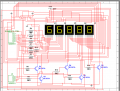
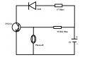
I would like to know and need help from you guys on how to build (wire up ) a automatic dimmer circuit to control multiplexed 5 individual common anode display and or mini bullet type incandescent bulbs ?
Need help with specific automatic dimmer circuit.
- Thread starter schematicsman
- Start date