Need help with resistor

Thread Starter

beeson76

Joined Apr 19, 2010
211
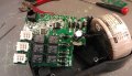
Here is a resistor I need to replace. The bands are brown, red, gray, and gray, or silver, and the final band is gold.

A picture is included. Can anyone tell me where to get one.

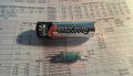
From my calculations it is a 1200M ohm resistor, using it as a gray band. I figure it was probably a 5 watt resistor, but I put a AA battery next to it for reference. I cant find a 1200M ohm resistor anywhere, so I figure I am mistaken.

Any help is greatly appreciated.

Thanks
 

Attachments

Thread Starter

beeson76

Joined Apr 19, 2010
211
I know that you cant see the colors as crisp as you could in read life, but does that look like silver?--its kinda got the metallic look of silver. I couldnt determine if it was silver or gray. If it is silver, then yes it would be .12 ohm.

As far as an inductor, could you please tell me more:).

Thanks
 

Adjuster

Joined Dec 26, 2010
2,148
Are you sure that it needs replacing anyway? It does not look as if it has overheated or been damaged, unless there is a blowout on the parts we can't see or maybe some small fracture.

If it appears open then it probably is faulty, but remember that if it is really 0.12Ω this may be hard to tell from a short-circuit with a simple meter.

Where is it from - a power amplifier, perhaps an emitter resistor?
 

#12

Joined Nov 30, 2010
18,224
Measure it. 1200M resistors probably exist but they would be long with a spiral on them to keep the resistance path long and leakage to a minimum. I don't think that is a 1200M resistor. Even if it was, it wouldn't fail, "shorted". It simply isn't possible.

If it has nearly zero ohms, you read it wrong.
 

Adjuster

Joined Dec 26, 2010
2,148
Measure it. 1200M resistors probably exist but they would be long with a spiral on them to keep the resistance path long and leakage to a minimum. I don't think that is a 1200M resistor. Even if it was, it wouldn't fail, "shorted". It simply isn't possible.

If it has nearly zero ohms, you read it wrong.
My bet is still on it being a really low resistance like 0.12Ω, or maybe an inductor. To measure that "right" would need a Kelvin (4-wire ) setup, which the OP probably is not using.

A simple ohm meter with two-wire leads won't do the job, but if you can run a known current through the resistor and measure the voltage developed using separate leads you might get within say ten percent of the truth.

We also might be able to advise better if we knew where this thing came from. Can you post a schematic ?
 
Last edited:

WBahn

Joined Mar 31, 2012
30,052
I agree with the others. 120milliohm, 5%.

It might just be the picture, but I think you can see a helical winding shape underneath the coating, which might be what is leading the OP to think there is an additional band between the multiplier and the tolerance bands.

I don't see any way this is a 4W resistor, it's physical size is too small for any 4W range resistor I've ever worked with. It most especially is not a 1200Mohm 4W resistor. To get 4W into a 1200Mohm resistor, you would have to have a nearly 70,000Vrms across it.
 

Adjuster

Joined Dec 26, 2010
2,148
Once more, a diagram or at least a mention of where it came from would be a big help. Generally (with a few exceptions) resistors of more than 10MΩ or so belong to pretty specialised low - current or high - voltage circuits.

Very low resistors are more commonly found, especially for current monitoring in things like power supplies, or perhaps to add a bit of DC negative feedback in an amplifier output stage to help stabilise the bias current. In a big audio power amplifier they are constrained to be pretty low value, as they affect the output impedance, and would waste more power if bigger
 
Last edited:

Thread Starter

beeson76

Joined Apr 19, 2010
211
Sorry for the delay. I couldnt get these pictures taken until this morning.

This is a Control Box for a bed. For example Bed up and down, etc.

There is a LED that keeps blinking really fast, so I figured it would be a capacitor. I replaced a MOSFET on it (it was just a guess, and it didnt fix the problem:)--it was tough because it was surface mounted, so I kinda piggybacked the new one onto the old one, so you would see a "mess" up there if you look at the pictures really good:)

So the next thing I could take a stab on was the big capacitor. I piggy backed the new capacitor on the back of the board and I could almost swear the LED stopped flashing, but then started flashing again after a few seconds, so I figured the new capacitor got blown...next thing was the big resistor:) And that is where I am at right now.

Its certainly a project to learn from. I dont have a schematic or anything, so this is just taking blind shots in the dark.

Thanks for any help given or suggested. I love the learning, even if it leads to failure and disappointment:) Im learning a little bit off this project.
 

Attachments

panic mode

Joined Oct 10, 2011
2,746
do you have multimeter? are you sure resistor is defective? at least i see no signs of damage (does not mean much but usually busted resistors are easy to spot, so problem may be elsewhere...)
 
Top