Need help with my LED project

Thread Starter

Jay Jay 3

Joined Aug 5, 2017
10
Hi guys,

My project is A portable energy efficient rechargeable LED lamp.I have been working on my project for quiet some time and i haven't had any luck getting it to work as intended. I would really appreciate it if you could help me with my design since i am not an experienced in circuit design.

Let me give you specification for the part of my project.
- I have to use DC-DC converter circuit in boost configuration to boost from 6V battery (12AH) to 15V as a source to drive the LEDs.
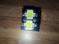
- I have to use PWM (ranging 10%-90% duty cycle) to control illumination of the 2 LEDs (each 12V 10W at 800 lumens)

IMG_20170930_144335.jpg

If you check my circuit i use PIC16F627A microcontroller to generate the PWM. I use LT1170 IC for DC-DC converter circuit to boost to 12V (i can boost it to 15V but i used the circuit from the datasheet of the LT1170 IC). I used mosfet IRF540 to drive the LEDs. I am using the LEDs in parallel because i want 600 lumens of light from the LEDs at 50% duty cycle. One 12V 10W LED provides 800 lumens max and i want 1200 lumens at 100% duty cycle and also taking into considerations of voltage of 12V when i used LEDs in parallel thats why i am using 2 LEDs in parallel.

When i tested my circuit i get current through the load to be 200mA. Now i know that i have to use constant current source to drive the LEDs but i dont how to design the constant current source. I have to provide atleast 1.2A current to my LEDs for it to work at 1200 lumens brightness @ 1.2A. I am not getting that current. Can anyone give suggestions on how can i get the current of 1.2A from the LT1170 IC?

Note: Keeping in mind that i am using 6V 12AH rechargeable battery as source for the DC-Dc converter and the PICMicontroller. The two switches that i have connected to the PIC are used for varying PWM duty cycle.
 
Last edited:

Dodgydave

Joined Jun 22, 2012
11,395
You don't need the pwm pic,!!!

the LT1171 can give out 2.5 amps depending on the inductor and diode, then all you need is a simple two transistor constant current source using a mosfet.


led_driving_and_controlling_methods_14.png
 

BobTPH

Joined Jun 5, 2013
11,515
Well, for one thing, the IRF540 will not be anywhere near fully on at 5V on the gate. It might have a resistance as high as 2 Ohms when the gate is driven by a 5V micro.

You need to use a logic level MOSFET like IRLZ44N, which is fully on at 5V, and has an on resistance of 0.04 Ohms at 4V.

Second problem is that you are driving the LED with a voltage source. You need a constant current driver. You might even find one that has the step up function built in.

Bob
 

PeteHL

Joined Dec 17, 2014
580
It is bad practice to connect two or more LEDs in parallel. According to Don Klipstein,

"Although this (LEDs in parallel) usually works, it is not reliable. LEDs become more conductive as they warm up, which may lead to unstable current distribution through paralleled LEDs. LEDs in parallel need their own individual dropping resistors."

In your case, you aren't using dropping resistors, so if you must have the LEDs in parallel, that would require a separate regulation circuit for each LED.
 

Thread Starter

Jay Jay 3

Joined Aug 5, 2017
10
Well, for one thing, the IRF540 will not be anywhere near fully on at 5V on the gate. It might have a resistance as high as 2 Ohms when the gate is driven by a 5V micro.

You need to use a logic level MOSFET like IRLZ44N, which is fully on at 5V, and has an on resistance of 0.04 Ohms at 4V.

Second problem is that you are driving the LED with a voltage source. You need a constant current driver. You might even find one that has the step up function built in.

Bob
Ok Thanks

Can you name a relevant constant current driver IC with step up function? I checked online and I found a lot of expensive ICs that i cant afford. If you know any ICs that I can use to drive the LEDs? Plz let me Thanks again for the feedback I appreciate it
 

Thread Starter

Jay Jay 3

Joined Aug 5, 2017
10
An LED that is blinding you with 10W is going to get very hot. How will you cool it so it doesn't melt?
Yes The led is bright enough to blind you with just 400mA of current so I have experienced it first hand. I am aware of the heating problem with the LEDs so I am using big enough heat sink to prevent over heating the LEDs.
IMG_20171001_234628.jpg
 

Thread Starter

Jay Jay 3

Joined Aug 5, 2017
10
It is bad practice to connect two or more LEDs in parallel. According to Don Klipstein,

"Although this (LEDs in parallel) usually works, it is not reliable. LEDs become more conductive as they warm up, which may lead to unstable current distribution through paralleled LEDs. LEDs in parallel need their own individual dropping resistors."

In your case, you aren't using dropping resistors, so if you must have the LEDs in parallel, that would require a separate regulation circuit for each LED.
Thank you
I wasn't aware of that.
If I connect the LEDs in series and I provide a constant current source it will work?
 

Attachments

PeteHL

Joined Dec 17, 2014
580
Thank you
I wasn't aware of that.
If I connect the LEDs in series and I provide a constant current source it will work?
Absolutely.

You could use LM317T linear voltage regulator configured as a current source. At least some of the data sheets for this regulator would give you a schematic as to how to configure it as a current source. Output current is a function of resistance of resistor connected from pin 1 to pin 3 of the regulator.

The LT1170 would have to be set to boost voltage at input to LM317T equal to the sum of the voltage drops across the series-connected LEDs and about 3V headroom, so 27V.
 
Last edited:

PeteHL

Joined Dec 17, 2014
580
In general I would say that the amp-hours of your battery is significantly underrated for what you want to do. This is assuming that your battery is a gel cell (lead acid) type.

To a certain extent it does depend on the purpose and how you would be using the light.

For example, if a typical continuous current through the LEDs in series was 500 mA, then load power is 12W.

That would mean that the battery must supply more than 2 Amp continuous current. A rule of thumb for lead acid batteries is that the minimum AH rating of the battery should be 20 times continuous current drawn. Thus the minimum AH rating would need to be 40 AH.
 

Thread Starter

Jay Jay 3

Joined Aug 5, 2017
10
In general I would say that the amp-hours of your battery is significantly underrated for what you want to do. This is assuming that your battery is a gel cell (lead acid) type.

To a certain extent it does depend on the purpose and how you would be using the light.

For example, if a typical continuous current through the LEDs in series was 500 mA, then load power is 12W.

That would mean that the battery must supply more than 2 Amp continuous current. A rule of thumb for lead acid batteries is that the minimum AH rating of the battery should be 20 times continuous current drawn. Thus the minimum AH rating would need to be 40 AH.
As long as the battery lasts for 1 hours than I can use the 12AH.
 

Thread Starter

Jay Jay 3

Joined Aug 5, 2017
10
Absolutely.

You could use LM317T linear voltage regulator configured as a current source. At least some of the data sheets for this regulator would give you a schematic as to how to configure it as a current source. Output current is a function of resistance of resistor connected from pin 1 to pin 3 of the regulator.

The LT1170 would have to be set to boost voltage at input to LM317T equal to the sum of the voltage drops across the series-connected LEDs and about 3V headroom, so 27V.
I took your advice and tested my circuit using LM317 as constant current source at the output of DC-DC boost converter I still get 200mA current well i need 800mA. That's because the LT1170 IC is only providing 230mA current at its output i am surprised why?
 

Thread Starter

Jay Jay 3

Joined Aug 5, 2017
10
The battery I am using can provide 3A current. Input to the DC-DC boost converter (using LT1170 IC) is the battery and so i am boosting 6V to 24V. At the output of the DC-DC converter i have LM317 constant current source circuit. Can LM317 draw more current that the LT1170 ?
 

BobTPH

Joined Jun 5, 2013
11,515
If you are boosting from 6V to 24V, you would need 3.2A to get 800mA at the output, if the converter was 100% efficient.

With a more likely efficiency of 80% that goes up to 4A.

Have you measured the output voltage of the LT1170 and the current at the battery?

Bob
 

Thread Starter

Jay Jay 3

Joined Aug 5, 2017
10
If you are boosting from 6V to 24V, you would need 3.2A to get 800mA at the output, if the converter was 100% efficient.

With a more likely efficiency of 80% that goes up to 4A.

Have you measured the output voltage of the LT1170 and the current at the battery?

Bob
I get output of 24V @ 200mA when I connect two 12V LEDs in series.
 

PeteHL

Joined Dec 17, 2014
580
The battery I am using can provide 3A current. Input to the DC-DC boost converter (using LT1170 IC) is the battery and so i am boosting 6V to 24V. At the output of the DC-DC converter i have LM317 constant current source circuit. Can LM317 draw more current that the LT1170 ?
The problem is that if the current supplied by the battery is 3A or greater, then the voltage of the battery droops to less than its rated voltage of 6V. That means that the LT1170 has to boost voltage even further to supply 27V to the LM317T regulator.

As Bob TPH suggests, you should try measuring current supplied by the battery, voltage at output of the boosting converter LT1170. Also measure voltage of the battery under load.

Even if you can get 800 mA running through the LEDs, then doing so will quickly ruin the battery. That is because the gel cell battery that you are using has a shortened useful life if you choose to continuously draw more than 600 mA from the battery. That is,

Amp Hours/ I = 20 (hours)
I = 12 A/20
I = 600 mA

Lead acid batteries are not capable of delivering a lot of current (relative to the size of the battery) without being quickly ruined.

Probably a 12V gel cell battery would be more appropriate for what you want to do than 6V, and not physically too much bigger than your 6V battery.

(Edited calculation of 600 mA current from the battery equivalent to C/20. I've always found "C/X" as being a little awkward :(.)
 
Last edited:

Thread Starter

Jay Jay 3

Joined Aug 5, 2017
10
The problem is that if the current supplied by the battery is 3A or greater, then the voltage of the battery droops to less than its rated voltage of 6V. That means that the LT1170 has to boost voltage even further to supply 27V to the LM317T regulator.

As Bob TPH suggests, you should try measuring current supplied by the battery, voltage at output of the boosting converter LT1170. Also measure voltage of the battery under load.

Even if you can get 800 mA running through the LEDs, then doing so will quickly ruin the battery. That is because the gel cell battery that you are using has a shortened useful life if you choose to continuously draw more than 600 mA from the battery. That is,

Amp Hours/ I = 20 (hours)
I = 12 A/20
I = 600 mA

Lead acid batteries are not capable of delivering a lot of current (relative to the size of the battery) without being quickly ruined.

Probably a 12V gel cell battery would be more appropriate for what you want to do than 6V, and not physically too much bigger than your 6V battery.

(Edited calculation of 600 mA current from the battery equivalent to C/20. I've always found "C/X" as being a little awkward :(.)
Thanks I'll used the 12V battery while testing my circuit.
 
Top