Need help with making a simple circuit that lights up a LED when a specific frequency is present

Thread Starter

chboizz1

Joined Aug 10, 2015
11
Hello folks,

I am relatively new to RF circuits, so please bear with me. (Note: this is not for homework or anything, but rather for personal experience)

I am trying to build a simple circuit with an antenna that will pick up nearby frequencies, filter out anything that isnt within around a 400Mhz to 800Mhz range and then light up a LED if this range of frequency signal is present.

I assume that the circuit should not be too complicated since all it should do is detect the "presence" of a signal and not actually decode its information signal.

I have done alot of reading up on band pass filters and resonant circuits and asked questions on other forms, but to be honest I am at a complete loss.

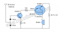
I have studied some RF signal detectors online such as this simple broad signal detector, but as it is, it detects a huge range of frequencies so I would like to be able to control the range of frequencies it detects.

Thanks,
 

Attachments

MikeML

Joined Oct 2, 2009
5,444
Do a search for Field Strength Meter in the Ham radio context.

Such things are usually not too sensitive, meaning that the transmitter being detected has to emit a substantial power level (hundreds of mW to Watts), and the distance from the FSM to the emitter is only a few feet...

To get an untuned bandwidth of an octave or so, you will likely have to cascade a low-pass filter with a high-pass filter. A parallel tuned LC tank is likely to have too narrow a response. Or you could have a tuning control, but would have to know the frequency of what you are trying to detect ahead of time.
 

Thread Starter

chboizz1

Joined Aug 10, 2015
11
Sorry, I forgot to mention I want the antenna to be relatively small, so im generally assuming that signal that this detector will be detecting will be basically aiming straight at it.
 

MikeML

Joined Oct 2, 2009
5,444
Sorry, I forgot to mention I want the antenna to be relatively small, so im generally assuming that signal that this detector will be detecting will be basically aiming straight at it.
This shows that you are naive about how antennas work... A broad-band directional antenna for your desired frequency range is on the order of a half meter by half meter. Think roof-mounted UHF over-the-air TV antenna.
 

Thread Starter

chboizz1

Joined Aug 10, 2015
11
Thanks for the reply, but I thought that some simple DIY mobile signal detectors (which I thought was on the magnitude of around 900Mhz to 3Ghz depending on carrier/etc) had relatively small antennas (1-2 inches).
 

KJ6EAD

Joined Apr 30, 2011
1,581
All other factors being equal, which they never are, antenna size is inversely proportional to frequency. Your assertion about the size of antenna for frequencies ≥ 900 MHz may be correct but so is MikeML's statement.
 

pwdixon

Joined Oct 11, 2012
488

dl324

Joined Mar 30, 2015
16,943
I am trying to build a simple circuit with an antenna that will pick up nearby frequencies, filter out anything that isnt within around a 400Mhz to 800Mhz range and then light up a LED if this range of frequency signal is present.
Google band pass filter.
 

Thread Starter

chboizz1

Joined Aug 10, 2015
11
Hello, I have been reading up on band pass filters and resonant circuits but its not very intuitive on how it fits into the circuit as a whole and also pwdixon, I am not trying to specifically build a cell phone detector either but rather be able to build a circuit for a targeted frequency range rather than a wide frequency range.

Thanks,
 

dl324

Joined Mar 30, 2015
16,943
I have been reading up on band pass filters and resonant circuits but its not very intuitive on how it fits into the circuit as a whole
The band pass filter lets the frequencies of interest pass. Depending on the nature of the signals being passed, you use them or some other circuit to turn on the LED indicator.
 

Thread Starter

chboizz1

Joined Aug 10, 2015
11
After taking MikeML's advice, I looked into some a relatively simple Field Strength Meter design.
I have attached the schematic with a theoretical L and C value which is suppose to tune the LC circuit to 500Mhz. I would like to ask if this current schematic is even correct and if I would be able to replace the ammeter with a LED instead to measure signal strength. Also would this circuit require a battery?

IMG_2612.JPG
 
Top