 Facebook
 Google
 GitHub
 Linkedin
So I have a headlight system, we converted from the halogen to the Xenon style
Halogen truck operation:
The BCM on this truck provides power to the low beam. When the high beams are activated the low beam power circuit is shut off, and power is sent to the high beam circuit only
Xenon Truck operation:
The BCM powers the low beam circuit constantly(the ballast has an independent power supply). When high beams are activated, the low beam circuit stays on, BUT power is also applied on the "high beam" to open the shutters
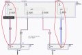
What I need to achieve is having the high beam circuit on the Halogen truck to send power to low beam circuit(or power with a relay or transistor). But without back feeding power to the now currently not active low beam circuit on the BCM. The transition has to be almost instant as if the ballasts suddenly loose their "on" input signal they start to act FUNKY.
Low beams on: acts normal
Switched to high beams: power or a signal is sent from the high beam circuit ONLY to keep lows activated, as well as power highs
Switched back to low: power/signal from truck returns to lights for low beam circuit, high beam has no power
I desperatly tried re coding the BCM, but it refused to swap its operating procedure.
I have spent hours googling, tried many different circuit lay outs in two different simulators, but just can't seem to get the result I want. I'm fairly certain I am over thinking this. I do not wanna just use a few diodes, since each it will see over 3 amps, and with the collapse the the shutter coil i don't wanna blow a little diode out. I first attempted to use 2 pmosfets as "reverse current protection" but since its not actually reverse current and the drain side of the mosfet is floating, it never opens, so current would still back feed
Halogen truck operation:
The BCM on this truck provides power to the low beam. When the high beams are activated the low beam power circuit is shut off, and power is sent to the high beam circuit only
Xenon Truck operation:
The BCM powers the low beam circuit constantly(the ballast has an independent power supply). When high beams are activated, the low beam circuit stays on, BUT power is also applied on the "high beam" to open the shutters
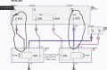
What I need to achieve is having the high beam circuit on the Halogen truck to send power to low beam circuit(or power with a relay or transistor). But without back feeding power to the now currently not active low beam circuit on the BCM. The transition has to be almost instant as if the ballasts suddenly loose their "on" input signal they start to act FUNKY.
Low beams on: acts normal
Switched to high beams: power or a signal is sent from the high beam circuit ONLY to keep lows activated, as well as power highs
Switched back to low: power/signal from truck returns to lights for low beam circuit, high beam has no power
I desperatly tried re coding the BCM, but it refused to swap its operating procedure.
I have spent hours googling, tried many different circuit lay outs in two different simulators, but just can't seem to get the result I want. I'm fairly certain I am over thinking this. I do not wanna just use a few diodes, since each it will see over 3 amps, and with the collapse the the shutter coil i don't wanna blow a little diode out. I first attempted to use 2 pmosfets as "reverse current protection" but since its not actually reverse current and the drain side of the mosfet is floating, it never opens, so current would still back feed
Attachments
-
 111.5 KB Views: 9
 -
 99.8 KB Views: 9
Last edited:


.png")


