 Facebook
 Google
 GitHub
 Linkedin
Need help with LTSPICE variable ESR modelling for Ceramic Capacitor
- Thread starter tahsina
- Start date
Scroll to continue with content
Pretty tough to advise you when you have provided no useful information in your post. It sounds like you want to use a behavioral resistor, which may be possible depending on which version of LTspice you are using. Alternatively, another simulator may be the ticket to solving your problem. Post the .asc file you are using along with any symbols and subcircuits you are using.Hello I am trying to model a variable ESR for Ceramic Capcitor and trying to match the datasheet frequency vs ESR graph in log scale, can someone please validate I am modelling the right circuit? Please and thank you
I have seen a frequency dependent inductor modeled by using the "table" construct. Seems like it would be possible to do a similar thing with a capacitor.
Here is the example of making frequency dependent inductors and resistors. AFAIK the syntax and semantics for this construction is undocumented in the LTspice documentation, but may be available in the Pspice documentation. It does seem to work however. N.B. This was not my discovery it was shown to me by @Bordodynov.

Hi I have attached the circuit and the waveform
Attachments
-
 592.3 KB Views: 11
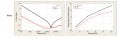
Agreed, here is the circuit and the log graph, the second attachment is for the waveform I am trying to match withPretty tough to advise you when you have provided no useful information in your post. It sounds like you want to use a behavioral resistor, which may be possible depending on which version of LTspice you are using. Alternatively, another simulator may be the ticket to solving your problem. Post the .asc file you are using along with any symbols and subcircuits you are using.
I have seen a frequency dependent inductor modeled by using the "table" construct. Seems like it would be possible to do a similar thing with a capacitor.
Attachments
-
 592.3 KB Views: 13
 -
 170.4 KB Views: 12
")
I have a couple of questions:Agreed, here is the circuit and the log graph, the second attachment is for the waveform I am trying to match with
- Did you watch the video mentioned by @ericgibbs in post #4? Was it helpful?
- Did you know that the spice model of a capacitor is more complicated than you might think?

- Are you familiar with the use of the table function?
- Did you understand what was happening in the resistor example of post#3
- Would expressing the capacitance in terms of charge be helpful?
There is also a general nonlinear capacitor available. Instead of specifying the capacitance, one writes an expression for the charge.
LTspice will compile this expression and symbolically differentiate it with respect to all the variables, finding the partial derivative's that correspond to capacitances.
Syntax: Cnnn n1 n2 Q=<expression> [ic=<value>] [m=<value>]
There is a special variable, x, that means the voltage across the device. Therefore, a 100pF constant capacitance can be written as
Cnnn n1 n2 Q=100p*x
A capacitance with an abrupt change from 100p to 300p at zero volts can be written as
Cnnn n1 n2 Q=x*if(x<0,100p,300p)
This device is useful for rapidly evaluating the behavior of a new a hypothetical charge model for, e.g., a transistor.
Last edited:
@Papabravo and @ericgibbs here is the circuit attached,
%%%%%%%%%%%%%%%%%%%%%%%%%% Cap data
CeraLink
Capacitor for fast-switching semiconductors
Series/Type: Flex Assembly (FA) series
Ordering code: B58035U*
Date: 2019-09-25
Version: 6.2
- Did you watch the video mentioned by @ericgibbs in post #4? Was it helpful?- That was helpful yet not sure I am understanding how I can match the Ceramic cap ESR vs Frequency log curve with it
- Did you know that the spice model of a capacitor is more complicated than you might think? I am well aware, this is my stab at it for the 5th time and I am trying to understand the ceramic capacitor ESR change as the frequency changed, I am using Ceralink caps for my DC link and the frequency change gives me ESR that varies from 2 ohm to 7mohm, I am trying to model how I can explain the capacitor characteristics for a 12khz inverter switching application. (Did Switching model in Simulink now want to create an actual ceramic model that I can drop and replace the ideal capacitor model in simulink)
- Are you familiar with the use of the table function?- I am not, in the past I have changed Battery ESR and inductance to model my problem but this is the first time I am seeing something like this
- Did you understand what was happening in the resistor example of post#3- My understanding was the resistive behavior vs the inductive behavior of a frequency response, correct me if I am wrong.
%%%%%%%%%%%%%%%%%%%%%%%%%% Cap data
CeraLink
Capacitor for fast-switching semiconductors
Series/Type: Flex Assembly (FA) series
Ordering code: B58035U*
Date: 2019-09-25
Version: 6.2
Attachments
-
4.1 KB Views: 6
My question in #4 was to see if you understood that there was an undocumented way to express a resistance that was a complex number. This gives you a resistor that is a function of frequency which is something that I think you are after. To get the characteristic V-shape you need to construct an ESR that gets large at high frequencies. That should be your starting point.
There appear to be two ways to do this. You can arrange for the real part of the impedance to grow with frequency which will dissipate real power and have other potentially undesirable effects, or you can have the imaginary part grow with frequency which means the capacitor will start looking like an inductor.
There appear to be two ways to do this. You can arrange for the real part of the impedance to grow with frequency which will dissipate real power and have other potentially undesirable effects, or you can have the imaginary part grow with frequency which means the capacitor will start looking like an inductor.
Realistic capacitor model including ESR and ESLMy question in #4 was to see if you understood that there was an undocumented way to express a resistance that was a complex number. This gives you a resistor that is a function of frequency which is something that I think you are after. To get the characteristic V-shape you need to construct an ESR that gets large at high frequencies. That should be your starting point.
There appear to be two ways to do this. You can arrange for the real part of the impedance to grow with frequency which will dissipate real power and have other potentially undesirable effects, or you can have the imaginary part grow with frequency which means the capacitor will start looking like an inductor.
I found this one, not sure how I would model the P and S you described, but that is exactly what I am trying to do, cause with frequency there will be real ESR and then non idealish ESR...
I don't understand what you mean by "how I would model P and S". I don't think I ever made reference to quantities P and S. Can you help me out here?Realistic capacitor model including ESR and ESL
I found this one, not sure how I would model the P and S you described, but that is exactly what I am trying to do, cause with frequency there will be real ESR and then non idealish ESR...
Here would be my first order approach to the modeling:
- Determine the self-resonant frequency of your capacitor. e.g. 5 MHz.
- Compute the value of Lser from the value of the capacitance and Lser. e.g. C = 4.7uF with a self resonant frequency of 5 MHz.
\( L_{ser}\;=\;\cfrac{1}{\omega^2C} \)
= 2.15.6 pH - Pick a nominal value for ESR like 1 milliohm
- Run the simulation

Last edited:
@ericgibbs and @Papabravo Attached the model I started working on now, Maybe I misunderstood what you said (It happens a lot to me) I have added a practical model of the Ceralink model that I found from the manufacturer datasheet, I am going to try to understand how it relates to the table function, then I dont know if it still represents what we should call a realistic model for the capacitor, my objective is to match the ESR vs Frequency log graph, I will read all your comments again, I am definitely missing something basic.

Attachments
-
1.6 KB Views: 6
.subckt B58031I9254M062_0.25uF_LP_TD A1 A2
+ esr=20.0m esl=2.7n captemp=85 fg=10
RIN A1 func1 1u
R0 B1 func1 100
R1 func1 21 20
C1 21 B1 5µ Rser=0 Rpar=0
R2 func1 31 1
C2 31 B1 3µ Rser=0 Rpar=0
R3 func1 41 150m
C3 41 B1 2.8µ Rser=0 Rpar=0
R4 func1 51 35m
C4 51 B1 2.4µ Rser=0 Rpar=0
R5 func1 61 'esr'
C5 61 B1 1µ Rser=0 Rpar=0
R6 mid B1 100Meg
C6 B2 mid {1/(2*pi*fg*100Meg)} Rser=0 Rpar=0
B1 101 A2 V=V(B1,mid)*V(B1,mid)
R7 int 101 100Meg
C7 A2 int {1/(2*pi*fg*10*100Meg)} Rser=0 Rpar=0
B2 vaceff A2 V=limit(Sqrt(V(int,A2)),0.5,7.1)
R8 vaceff A2 100Meg
B3 B1 B2 I=0.000001*(4*(13.151561603982+(0.18392685302364+(0.0013480077966704+(-5.2876622060756*pow(10,-7)+(-4.2445410907105*pow(10,-7)+2.0702248668382*pow(10,-9)*limit(captemp,-50,150))*limit(captemp,-50,150))*limit(captemp,-50,150))*limit(captemp,-50,150))*limit(captemp,-50,150)+limit(V(vaceff,A2),0.5,7.1)*(2.133883766835+(-0.0056987119667124+(-0.00037124601416288+(7.4474115578529*pow(10,-8)+(5.9782268883247*pow(10,-8)-2.9158096716032*pow(10,-10)*limit(captemp,-50,150))*limit(captemp,-50,150))*limit(captemp,-50,150))*limit(captemp,-50,150))*limit(captemp,-50,150)))*exp(2*limit(abs(V(mid,B2)),0,1000)/(318.59445279753+(-1.7212936538836+(0.0090574524461542+(0.00037141237268879+(-4.6262349014818*pow(10,-6)+1.4933489534859*pow(10,-8)*limit(captemp,-50,150))*limit(captemp,-50,150))*limit(captemp,-50,150))*limit(captemp,-50,150))*limit(captemp,-50,150)+limit(V(vaceff,A2),0.5,7.1)*(-9.6283980004698+(0.20606880862834+(-1.0508102481241*pow(10,-5)+(-5.2311601787154*pow(10,-5)+(6.515823804904*pow(10,-7)-2.1033083851914*pow(10,-9)*limit(captemp,-50,150))*limit(captemp,-50,150))*limit(captemp,-50,150))*limit(captemp,-50,150))*limit(captemp,-50,150)))+2*(954.74584220723+(-1.5595832226017+(-0.0010201159636711+(9.2323210438197*pow(10,-5)+(-2.1337387017379*pow(10,-6)+8.8798302926678*pow(10,-9)*limit(captemp,-50,150))*limit(captemp,-50,150))*limit(captemp,-50,150))*limit(captemp,-50,150))*limit(captemp,-50,150)+limit(V(vaceff,A2),0.5,7.1)*(-4.2900053829397+(0.061447376600945+(-0.00082375257898532+(-1.3003269075802*pow(10,-5)+(3.0052657770956*pow(10,-7)-1.250680322911*pow(10,-9)*limit(captemp,-50,150))*limit(captemp,-50,150))*limit(captemp,-50,150))*limit(captemp,-50,150))*limit(captemp,-50,150)))/(318.59445279753+(-1.7212936538836+(0.0090574524461542+(0.00037141237268879+(-4.6262349014818*pow(10,-6)+1.4933489534859*pow(10,-8)*limit(captemp,-50,150))*limit(captemp,-50,150))*limit(captemp,-50,150))*limit(captemp,-50,150))*limit(captemp,-50,150)+limit(V(vaceff,A2),0.5,7.1)*(-9.6283980004698+(0.20606880862834+(-1.0508102481241*pow(10,-5)+(-5.2311601787154*pow(10,-5)+(6.515823804904*pow(10,-7)-2.1033083851914*pow(10,-9)*limit(captemp,-50,150))*limit(captemp,-50,150))*limit(captemp,-50,150))*limit(captemp,-50,150))*limit(captemp,-50,150))))/((318.59445279753+(-1.7212936538836+(0.0090574524461542+(0.00037141237268879+(-4.6262349014818*pow(10,-6)+1.4933489534859*pow(10,-8)*limit(captemp,-50,150))*limit(captemp,-50,150))*limit(captemp,-50,150))*limit(captemp,-50,150))*limit(captemp,-50,150)+limit(V(vaceff,A2),0.5,7.1)*(-9.6283980004698+(0.20606880862834+(-1.0508102481241*pow(10,-5)+(-5.2311601787154*pow(10,-5)+(6.515823804904*pow(10,-7)-2.1033083851914*pow(10,-9)*limit(captemp,-50,150))*limit(captemp,-50,150))*limit(captemp,-50,150))*limit(captemp,-50,150))*limit(captemp,-50,150)))*pow(exp(2*limit(abs(V(mid,B2)),0,1000)/(318.59445279753+(-1.7212936538836+(0.0090574524461542+(0.00037141237268879+(-4.6262349014818*pow(10,-6)+1.4933489534859*pow(10,-8)*limit(captemp,-50,150))*limit(captemp,-50,150))*limit(captemp,-50,150))*limit(captemp,-50,150))*limit(captemp,-50,150)+limit(V(vaceff,A2),0.5,7.1)*(-9.6283980004698+(0.20606880862834+(-1.0508102481241*pow(10,-5)+(-5.2311601787154*pow(10,-5)+(6.515823804904*pow(10,-7)-2.1033083851914*pow(10,-9)*limit(captemp,-50,150))*limit(captemp,-50,150))*limit(captemp,-50,150))*limit(captemp,-50,150))*limit(captemp,-50,150))))+exp(2*(954.74584220723+(-1.5595832226017+(-0.0010201159636711+(9.2323210438197*pow(10,-5)+(-2.1337387017379*pow(10,-6)+8.8798302926678*pow(10,-9)*limit(captemp,-50,150))*limit(captemp,-50,150))*limit(captemp,-50,150))*limit(captemp,-50,150))*limit(captemp,-50,150)+limit(V(vaceff,A2),0.5,7.1)*(-4.2900053829397+(0.061447376600945+(-0.00082375257898532+(-1.3003269075802*pow(10,-5)+(3.0052657770956*pow(10,-7)-1.250680322911*pow(10,-9)*limit(captemp,-50,150))*limit(captemp,-50,150))*limit(captemp,-50,150))*limit(captemp,-50,150))*limit(captemp,-50,150)))/(318.59445279753+(-1.7212936538836+(0.0090574524461542+(0.00037141237268879+(-4.6262349014818*pow(10,-6)+1.4933489534859*pow(10,-8)*limit(captemp,-50,150))*limit(captemp,-50,150))*limit(captemp,-50,150))*limit(captemp,-50,150))*limit(captemp,-50,150)+limit(V(vaceff,A2),0.5,7.1)*(-9.6283980004698+(0.20606880862834+(-1.0508102481241*pow(10,-5)+(-5.2311601787154*pow(10,-5)+(6.515823804904*pow(10,-7)-2.1033083851914*pow(10,-9)*limit(captemp,-50,150))*limit(captemp,-50,150))*limit(captemp,-50,150))*limit(captemp,-50,150))*limit(captemp,-50,150)))),2))+4*(511.21038275239+(3.497720881754+(-0.1693665933174+(-0.001224690558399+(3.9054764879159*pow(10,-5)-1.633595188483*pow(10,-7)*limit(captemp,-50,150))*limit(captemp,-50,150))*limit(captemp,-50,150))*limit(captemp,-50,150))*limit(captemp,-50,150)+limit(V(vaceff,A2),0.5,7.1)*(-45.90113906508+(-0.42909882024066+(0.023685541608873+(0.00017249162794352+(-5.5006711097407*pow(10,-6)+2.300838293638*pow(10,-8)*limit(captemp,-50,150))*limit(captemp,-50,150))*limit(captemp,-50,150))*limit(captemp,-50,150))*limit(captemp,-50,150)))*exp(2*limit(abs(V(mid,B2)),0,1000)/(7397.4417028849+(38.008740651017+(-2.2482311052243+(-0.016735307637858+(0.00052734652800512-2.2022308539132*pow(10,-6)*limit(captemp,-50,150))*limit(captemp,-50,150))*limit(captemp,-50,150))*limit(captemp,-50,150))*limit(captemp,-50,150)+limit(V(vaceff,A2),0.5,7.1)*(-702.6382656849+(-4.8613296856218+(0.31855022652028+(0.0023570855827969+(-7.427415887396*pow(10,-5)+3.1017335970609*pow(10,-7)*limit(captemp,-50,150))*limit(captemp,-50,150))*limit(captemp,-50,150))*limit(captemp,-50,150))*limit(captemp,-50,150))))/((7397.4417028849+(38.008740651017+(-2.2482311052243+(-0.016735307637858+(0.00052734652800512-2.2022308539132*pow(10,-6)*limit(captemp,-50,150))*limit(captemp,-50,150))*limit(captemp,-50,150))*limit(captemp,-50,150))*limit(captemp,-50,150)+limit(V(vaceff,A2),0.5,7.1)*(-702.6382656849+(-4.8613296856218+(0.31855022652028+(0.0023570855827969+(-7.427415887396*pow(10,-5)+3.1017335970609*pow(10,-7)*limit(captemp,-50,150))*limit(captemp,-50,150))*limit(captemp,-50,150))*limit(captemp,-50,150))*limit(captemp,-50,150)))*pow(1+exp(2*limit(abs(V(mid,B2)),0,1000)/(7397.4417028849+(38.008740651017+(-2.2482311052243+(-0.016735307637858+(0.00052734652800512-2.2022308539132*pow(10,-6)*limit(captemp,-50,150))*limit(captemp,-50,150))*limit(captemp,-50,150))*limit(captemp,-50,150))*limit(captemp,-50,150)+limit(V(vaceff,A2),0.5,7.1)*(-702.6382656849+(-4.8613296856218+(0.31855022652028+(0.0023570855827969+(-7.427415887396*pow(10,-5)+3.1017335970609*pow(10,-7)*limit(captemp,-50,150))*limit(captemp,-50,150))*limit(captemp,-50,150))*limit(captemp,-50,150))*limit(captemp,-50,150)))),2))+(-3.1467984880349*pow(10,-11)+(-7.0452432879438*pow(10,-13)+(1.8542384719005*pow(10,-15)+(6.6916314879812*pow(10,-20)+(1.0073642537315*pow(10,-17)+1.382791933716*pow(10,-15)*limit(captemp,-50,150))*limit(captemp,-50,150))*limit(captemp,-50,150))*limit(captemp,-50,150))*limit(captemp,-50,150)+limit(V(vaceff,A2),0.5,7.1)*(6.2935969760698*pow(10,-11)+(1.409048657593*pow(10,-12)+(-3.708475776609*pow(10,-15)+(-9.4248330816636*pow(10,-21)+(-1.4188228925796*pow(10,-18)-1.9475942728394*pow(10,-16)*limit(captemp,-50,150))*limit(captemp,-50,150))*limit(captemp,-50,150))*limit(captemp,-50,150))*limit(captemp,-50,150))))*ddt(V(B1,B2))
L1 B2 func2 'esl' Rser=0
ROUT func2 A2 1u
.ends
*
.subckt B58031I9254M062_0.25uF_LP_TD A1 A2Your .asc file is NFG without the symbol B5803x_500V_TD.asy and the associated subcircuit. Awaiting your reply.
+ esr=20.0m esl=2.7n captemp=85 fg=10
RIN A1 func1 1u
R0 B1 func1 100
R1 func1 21 20
C1 21 B1 5µ Rser=0 Rpar=0
R2 func1 31 1
C2 31 B1 3µ Rser=0 Rpar=0
R3 func1 41 150m
C3 41 B1 2.8µ Rser=0 Rpar=0
R4 func1 51 35m
C4 51 B1 2.4µ Rser=0 Rpar=0
R5 func1 61 'esr'
C5 61 B1 1µ Rser=0 Rpar=0
R6 mid B1 100Meg
C6 B2 mid {1/(2*pi*fg*100Meg)} Rser=0 Rpar=0
B1 101 A2 V=V(B1,mid)*V(B1,mid)
R7 int 101 100Meg
C7 A2 int {1/(2*pi*fg*10*100Meg)} Rser=0 Rpar=0
B2 vaceff A2 V=limit(Sqrt(V(int,A2)),0.5,7.1)
R8 vaceff A2 100Meg
B3 B1 B2 I=0.000001*(4*(13.151561603982+(0.18392685302364+(0.0013480077966704+(-5.2876622060756*pow(10,-7)+(-4.2445410907105*pow(10,-7)+2.0702248668382*pow(10,-9)*limit(captemp,-50,150))*limit(captemp,-50,150))*limit(captemp,-50,150))*limit(captemp,-50,150))*limit(captemp,-50,150)+limit(V(vaceff,A2),0.5,7.1)*(2.133883766835+(-0.0056987119667124+(-0.00037124601416288+(7.4474115578529*pow(10,-8)+(5.9782268883247*pow(10,-8)-2.9158096716032*pow(10,-10)*limit(captemp,-50,150))*limit(captemp,-50,150))*limit(captemp,-50,150))*limit(captemp,-50,150))*limit(captemp,-50,150)))*exp(2*limit(abs(V(mid,B2)),0,1000)/(318.59445279753+(-1.7212936538836+(0.0090574524461542+(0.00037141237268879+(-4.6262349014818*pow(10,-6)+1.4933489534859*pow(10,-8)*limit(captemp,-50,150))*limit(captemp,-50,150))*limit(captemp,-50,150))*limit(captemp,-50,150))*limit(captemp,-50,150)+limit(V(vaceff,A2),0.5,7.1)*(-9.6283980004698+(0.20606880862834+(-1.0508102481241*pow(10,-5)+(-5.2311601787154*pow(10,-5)+(6.515823804904*pow(10,-7)-2.1033083851914*pow(10,-9)*limit(captemp,-50,150))*limit(captemp,-50,150))*limit(captemp,-50,150))*limit(captemp,-50,150))*limit(captemp,-50,150)))+2*(954.74584220723+(-1.5595832226017+(-0.0010201159636711+(9.2323210438197*pow(10,-5)+(-2.1337387017379*pow(10,-6)+8.8798302926678*pow(10,-9)*limit(captemp,-50,150))*limit(captemp,-50,150))*limit(captemp,-50,150))*limit(captemp,-50,150))*limit(captemp,-50,150)+limit(V(vaceff,A2),0.5,7.1)*(-4.2900053829397+(0.061447376600945+(-0.00082375257898532+(-1.3003269075802*pow(10,-5)+(3.0052657770956*pow(10,-7)-1.250680322911*pow(10,-9)*limit(captemp,-50,150))*limit(captemp,-50,150))*limit(captemp,-50,150))*limit(captemp,-50,150))*limit(captemp,-50,150)))/(318.59445279753+(-1.7212936538836+(0.0090574524461542+(0.00037141237268879+(-4.6262349014818*pow(10,-6)+1.4933489534859*pow(10,-8)*limit(captemp,-50,150))*limit(captemp,-50,150))*limit(captemp,-50,150))*limit(captemp,-50,150))*limit(captemp,-50,150)+limit(V(vaceff,A2),0.5,7.1)*(-9.6283980004698+(0.20606880862834+(-1.0508102481241*pow(10,-5)+(-5.2311601787154*pow(10,-5)+(6.515823804904*pow(10,-7)-2.1033083851914*pow(10,-9)*limit(captemp,-50,150))*limit(captemp,-50,150))*limit(captemp,-50,150))*limit(captemp,-50,150))*limit(captemp,-50,150))))/((318.59445279753+(-1.7212936538836+(0.0090574524461542+(0.00037141237268879+(-4.6262349014818*pow(10,-6)+1.4933489534859*pow(10,-8)*limit(captemp,-50,150))*limit(captemp,-50,150))*limit(captemp,-50,150))*limit(captemp,-50,150))*limit(captemp,-50,150)+limit(V(vaceff,A2),0.5,7.1)*(-9.6283980004698+(0.20606880862834+(-1.0508102481241*pow(10,-5)+(-5.2311601787154*pow(10,-5)+(6.515823804904*pow(10,-7)-2.1033083851914*pow(10,-9)*limit(captemp,-50,150))*limit(captemp,-50,150))*limit(captemp,-50,150))*limit(captemp,-50,150))*limit(captemp,-50,150)))*pow(exp(2*limit(abs(V(mid,B2)),0,1000)/(318.59445279753+(-1.7212936538836+(0.0090574524461542+(0.00037141237268879+(-4.6262349014818*pow(10,-6)+1.4933489534859*pow(10,-8)*limit(captemp,-50,150))*limit(captemp,-50,150))*limit(captemp,-50,150))*limit(captemp,-50,150))*limit(captemp,-50,150)+limit(V(vaceff,A2),0.5,7.1)*(-9.6283980004698+(0.20606880862834+(-1.0508102481241*pow(10,-5)+(-5.2311601787154*pow(10,-5)+(6.515823804904*pow(10,-7)-2.1033083851914*pow(10,-9)*limit(captemp,-50,150))*limit(captemp,-50,150))*limit(captemp,-50,150))*limit(captemp,-50,150))*limit(captemp,-50,150))))+exp(2*(954.74584220723+(-1.5595832226017+(-0.0010201159636711+(9.2323210438197*pow(10,-5)+(-2.1337387017379*pow(10,-6)+8.8798302926678*pow(10,-9)*limit(captemp,-50,150))*limit(captemp,-50,150))*limit(captemp,-50,150))*limit(captemp,-50,150))*limit(captemp,-50,150)+limit(V(vaceff,A2),0.5,7.1)*(-4.2900053829397+(0.061447376600945+(-0.00082375257898532+(-1.3003269075802*pow(10,-5)+(3.0052657770956*pow(10,-7)-1.250680322911*pow(10,-9)*limit(captemp,-50,150))*limit(captemp,-50,150))*limit(captemp,-50,150))*limit(captemp,-50,150))*limit(captemp,-50,150)))/(318.59445279753+(-1.7212936538836+(0.0090574524461542+(0.00037141237268879+(-4.6262349014818*pow(10,-6)+1.4933489534859*pow(10,-8)*limit(captemp,-50,150))*limit(captemp,-50,150))*limit(captemp,-50,150))*limit(captemp,-50,150))*limit(captemp,-50,150)+limit(V(vaceff,A2),0.5,7.1)*(-9.6283980004698+(0.20606880862834+(-1.0508102481241*pow(10,-5)+(-5.2311601787154*pow(10,-5)+(6.515823804904*pow(10,-7)-2.1033083851914*pow(10,-9)*limit(captemp,-50,150))*limit(captemp,-50,150))*limit(captemp,-50,150))*limit(captemp,-50,150))*limit(captemp,-50,150)))),2))+4*(511.21038275239+(3.497720881754+(-0.1693665933174+(-0.001224690558399+(3.9054764879159*pow(10,-5)-1.633595188483*pow(10,-7)*limit(captemp,-50,150))*limit(captemp,-50,150))*limit(captemp,-50,150))*limit(captemp,-50,150))*limit(captemp,-50,150)+limit(V(vaceff,A2),0.5,7.1)*(-45.90113906508+(-0.42909882024066+(0.023685541608873+(0.00017249162794352+(-5.5006711097407*pow(10,-6)+2.300838293638*pow(10,-8)*limit(captemp,-50,150))*limit(captemp,-50,150))*limit(captemp,-50,150))*limit(captemp,-50,150))*limit(captemp,-50,150)))*exp(2*limit(abs(V(mid,B2)),0,1000)/(7397.4417028849+(38.008740651017+(-2.2482311052243+(-0.016735307637858+(0.00052734652800512-2.2022308539132*pow(10,-6)*limit(captemp,-50,150))*limit(captemp,-50,150))*limit(captemp,-50,150))*limit(captemp,-50,150))*limit(captemp,-50,150)+limit(V(vaceff,A2),0.5,7.1)*(-702.6382656849+(-4.8613296856218+(0.31855022652028+(0.0023570855827969+(-7.427415887396*pow(10,-5)+3.1017335970609*pow(10,-7)*limit(captemp,-50,150))*limit(captemp,-50,150))*limit(captemp,-50,150))*limit(captemp,-50,150))*limit(captemp,-50,150))))/((7397.4417028849+(38.008740651017+(-2.2482311052243+(-0.016735307637858+(0.00052734652800512-2.2022308539132*pow(10,-6)*limit(captemp,-50,150))*limit(captemp,-50,150))*limit(captemp,-50,150))*limit(captemp,-50,150))*limit(captemp,-50,150)+limit(V(vaceff,A2),0.5,7.1)*(-702.6382656849+(-4.8613296856218+(0.31855022652028+(0.0023570855827969+(-7.427415887396*pow(10,-5)+3.1017335970609*pow(10,-7)*limit(captemp,-50,150))*limit(captemp,-50,150))*limit(captemp,-50,150))*limit(captemp,-50,150))*limit(captemp,-50,150)))*pow(1+exp(2*limit(abs(V(mid,B2)),0,1000)/(7397.4417028849+(38.008740651017+(-2.2482311052243+(-0.016735307637858+(0.00052734652800512-2.2022308539132*pow(10,-6)*limit(captemp,-50,150))*limit(captemp,-50,150))*limit(captemp,-50,150))*limit(captemp,-50,150))*limit(captemp,-50,150)+limit(V(vaceff,A2),0.5,7.1)*(-702.6382656849+(-4.8613296856218+(0.31855022652028+(0.0023570855827969+(-7.427415887396*pow(10,-5)+3.1017335970609*pow(10,-7)*limit(captemp,-50,150))*limit(captemp,-50,150))*limit(captemp,-50,150))*limit(captemp,-50,150))*limit(captemp,-50,150)))),2))+(-3.1467984880349*pow(10,-11)+(-7.0452432879438*pow(10,-13)+(1.8542384719005*pow(10,-15)+(6.6916314879812*pow(10,-20)+(1.0073642537315*pow(10,-17)+1.382791933716*pow(10,-15)*limit(captemp,-50,150))*limit(captemp,-50,150))*limit(captemp,-50,150))*limit(captemp,-50,150))*limit(captemp,-50,150)+limit(V(vaceff,A2),0.5,7.1)*(6.2935969760698*pow(10,-11)+(1.409048657593*pow(10,-12)+(-3.708475776609*pow(10,-15)+(-9.4248330816636*pow(10,-21)+(-1.4188228925796*pow(10,-18)-1.9475942728394*pow(10,-16)*limit(captemp,-50,150))*limit(captemp,-50,150))*limit(captemp,-50,150))*limit(captemp,-50,150))*limit(captemp,-50,150))))*ddt(V(B1,B2))
L1 B2 func2 'esl' Rser=0
ROUT func2 A2 1u
.ends
*


Attachments
-
1.6 KB Views: 4
I am not sure why I am not getting the V curve like the datasheet
I don't understand why you cannot fix this problem when I open your schematic file:I am not sure why I am not getting the V curve like the datasheet


