Need help with LED's swap on board

Thread Starter

Omar Aziz

Joined Jun 19, 2015
8
Hi all,
It's great to know such a forum exists. I kept on looking for shops near me that could help, but that didn't go very well. Hope I can solve my problem here.

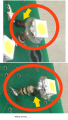
This board is the A/C, NAV buttons for my Lexus.
It had orange LED's before. I just wanted to take those out and put white ones in.


I got similar 3 mm LED's, soldered them, making sure of the polarity. But they didn't work.
Would anyone know what the problem is by looking at the board?


The other question is, these GREEN SMD's, I'm afraid to take out and put other SMD's I have and find that they won't work.


Sent from my iPhone using Tapatalk
 

#12

Joined Nov 30, 2010
18,224
White LEDs need a higher voltage. The voltage requirement goes like the rainbow, red, orange, yellow, green, blue....white.
I hope you didn't wreck anything on your Lexus control board.
 

KJ6EAD

Joined Apr 30, 2011
1,581
There appear to be two resistors in parallel controlling the current for each LED, a 560Ω and a 680Ω, marked 561 and 681 respectively. Their combined value is around 308Ω. You could probably replace the two resistors with two 470Ω resistors of the same size but unless your SMD soldering skills are better than what I see in the removed LED pads, there's a good chance you'll destroy the board in your efforts. I could suggest a few measurements to make to verify the guesses my calculations were based on but again, if you knew to make those measurements, you probably wouldn't be asking for the help you are. I'm afraid you may take this as unhelpful or even insulting but it's an honest appraisal of what I see.
 

#12

Joined Nov 30, 2010
18,224
I don't see any inductors on that board...which might be used in a voltage booster circuit. If the entire power supply is 2 AA batteries, you don't have enough voltage to fire a white led, no matter how you try to change resistors to affect the current.
 

Thread Starter

Omar Aziz

Joined Jun 19, 2015
8
I hope so too.


I thank you for being very honest and clear, I respect that.
But I would still like to know more, as I am a very fast learner.


The power that is being is supplied, is 13.8V I believe.
 

#12

Joined Nov 30, 2010
18,224
Oh. This is a control panel that is plugged into the car in order to operate. Right?
That would mean it is probably possible to fire up a white LED...or a row of them.
Now, did some brainiac design the board to work with 3.3 volts because that is considered, "logic level" in the 21st century? This is a, "need to know", and I don't know it.
 

Kermit2

Joined Feb 5, 2010
4,162
I highly doubt a logic level voltage has been routed to this accessory board. briefly jumper one set of those smd resistors with a standard 300 resistor, or a 270 ohm one( whichever is easiest to come by). just bend the leads and touch the across one of the resistors. It should light up at least dimly. The other possibilty is you have installed the LED backwards. They are polarity dependent.
 

JoeJester

Joined Apr 26, 2005
4,390
According to the chart at http://www.oksolar.com/led/led_color_chart.htm Orange LEDs have about 2.2 V Vf. So, the current flow is around 37 mA at 13.8Volts.

The white LED VF is about 3.6V and using the same resistors, the white LEDs would have about 33 mA, a difference of 4 mA. I don't know if that would be enough of a difference for me to worry about the brightness in the LED. Also bear in mind, those are probably Pulse Width Modulated controlled by the light/dark sensor somewhere on your dashboard.

Those green things seem to be switches to me as you are pressing down on a switch to activate one or more of the functions displayed.

Why do you want to change to white lights?
 

Thread Starter

Omar Aziz

Joined Jun 19, 2015
8
Oh. This is a control panel that is plugged into the car in order to operate. Right?
That would mean it is probably possible to fire up a white LED...or a row of them.
Now, did some brainiac design the board to work with 3.3 volts because that is considered, "logic level" in the 21st century? This is a, "need to know", and I don't know it.
Yes, this board goes in my car, and it has the buttons that control the climate, NAV, and audio.
 

KJ6EAD

Joined Apr 30, 2011
1,581
According to the chart at http://www.oksolar.com/led/led_color_chart.htm Orange LEDs have about 2.2 V Vf. So, the current flow is around 37 mA at 13.8Volts.

The white LED VF is about 3.6V and using the same resistors, the white LEDs would have about 33 mA, a difference of 4 mA. I don't know if that would be enough of a difference for me to worry about the brightness in the LED. Also bear in mind, those are probably Pulse Width Modulated controlled by the light/dark sensor somewhere on your dashboard.

Those green things seem to be switches to me as you are pressing down on a switch to activate one or more of the functions displayed.

Why do you want to change to white lights?
I think the green things are general illumination LEDs for the switch actuator legends. The orange ones are just for the semirectangular indicators on the actuator faces.
 

Thread Starter

Omar Aziz

Joined Jun 19, 2015
8
I highly doubt a logic level voltage has been routed to this accessory board. briefly jumper one set of those smd resistors with a standard 300 resistor, or a 270 ohm one( whichever is easiest to come by). just bend the leads and touch the across one of the resistors. It should light up at least dimly. The other possibilty is you have installed the LED backwards. They are polarity dependent.
Is this what you mean? This is a 220 ohm resistor that I had laying around. Haven't tried it yet. But afraid it's no good because of the size of it, it's too big like this to fit in the housing.
IMG_1758.JPG


According to the chart at http://www.oksolar.com/led/led_color_chart.htm Orange LEDs have about 2.2 V Vf. So, the current flow is around 37 mA at 13.8Volts.

The white LED VF is about 3.6V and using the same resistors, the white LEDs would have about 33 mA, a difference of 4 mA. I don't know if that would be enough of a difference for me to worry about the brightness in the LED. Also bear in mind, those are probably Pulse Width Modulated controlled by the light/dark sensor somewhere on your dashboard.

Those green things seem to be switches to me as you are pressing down on a switch to activate one or more of the functions displayed.

Why do you want to change to white lights?
I will not worry about how bright they are, because they are already bright enough, and they only come on when the associated button is pressed. Yes, there is a brightness ambient sensor on the dash that lights things up if I had the lighting on automatic.

The green SMD's are the ones that should always be on. I replaced them with a couple white SMD's that I have, and they worked fine, EXCEPT for the one's circled in the picture.

IMG_1759.JPG


SO, I have 2 issues now, getting those 2 SMD's to light up, and to get those LED's to light up!
Appreciate the help so far.


I have changed all the accent lighting in my car, going from the boring GREEN color to WHITE accenting, makes the car look more fresh and more modern.
 

JoeJester

Joined Apr 26, 2005
4,390
I think the green things are general illumination LEDs for the switch actuator legends. The orange ones are just for the semirectangular indicators on the actuator faces.
Upon further review, I do see the switch contacts.
 

Thread Starter

Omar Aziz

Joined Jun 19, 2015
8
Are there diodes under those two that won't light up?
By diodes do you mean the metal parts coming through the back of the board? then no.
It seems like something different is on the back, there are no direct contacts between what's on top of the board and what's on the bottom of the board.

IMG_1762.JPG

Here the SMD's not working.


And here I found that on one of the LED's connector to the board is missing. Could this be the cause to why the rest of the LED's didn't light up last time, because of this loose or no connection with this LED caused he rest to not light up?

IMG_1761.JPG

How do I fix it? There seems to be a very light line heading to the resistor "561", would I just solder it directly to that?


Lots of questions folks. Hope we can find a solution.
 

Kermit2

Joined Feb 5, 2010
4,162
How do you fix it?

Yes you solder directly to it. Put the lead of the LED through the hole and leave it long enough to bend over and touch the nearby SMD resistor. Then solder it there.
Also the 220 ohm resistor will be fine to test with you just touch the ends of the resistors legs across the SMD resistor. This should allow the white LED to come on. IF you have them soldered in the correct way. Remember they are polarized and they will NEVER light up if soldered in backwards.
 

Thread Starter

Omar Aziz

Joined Jun 19, 2015
8
So I replaced the top 2 SMD's that were working with the same SMD's that I have under, and now they don't light up.

I did this switch because I was getting different measurements on every location. Starting by 13V from the one further South, and then it varies from 5.8V to 6V and so on...

IMG_1763s.jpg
IMG_1764-b.jpg
 

Thread Starter

Omar Aziz

Joined Jun 19, 2015
8
I think I have officially given up. I need a shop or someone that I can pay and have them do the job.

It is reached the point where I do not know what I'm doing.

What shop should I look for who can do such a thing?
 

ScottWang

Joined Aug 23, 2012
7,400
Your attached photos were too large except the first post, please compress them to a appropriate size as 800*600 or 1024*768 before you upload them next time, I already did resize some of them, thank you.
 
Top