Need help with a pre built circuit board that controls led's but I want to control a small brushless pc fan.

Thread Starter

{tpc]

Joined Sep 16, 2025
13
Hi all, new here. I'm having a little trouble figuring this out, hopefully someone can point me in the right direction before I give up.

What I have is a small light timer commonly used to control leds for aquarium lights or plant leds. Basically you can set it for 4 hours, 8 hours, or 12 hours.

What I want to do is two fold. First I'd like to change the timing sequence to lower it, but that might be impossible and may be built into the chip, but more about that later.

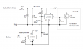
The other thing is I want it to spin a small dc computer fan. Seemed easy enough, until I hooked the fan up. It kind of chatters, but won't spin. There is very little voltage drop when I connect the fan, so it doesn't kill the output, but yet cant work. I can see it pulling current when I hook the fan up, and the fan by itself doesn't source a bunch of current, so not sure what is limiting it.

I thought it might need a flyback diode so I tryed a 1n4007, but no joy. Though its a modern fan so it might not need the diode anyway. The output comes off a A09T mosfet, which I believe is a 30v n channel mosfet. It also is switching the negative side on, as the positive is connected straight through to the source side. The microcontroller doesn't have an identifying mark, but is run off a 5v regulator, and has a what I think is a 16 mhz oscillator connected to it (H16.00).

Any thoughts? I've seen some posts on here with directions on how to make a circuit, but I thought I could make this work just for a different application.
 

Tonyr1084

Joined Sep 24, 2015
9,744
I hooked the fan up. It kind of chatters, but won't spin.
First, like panic mode said - we need to see a schematic. Photos may help too.
Second, does the fan run when connected to 12VDC? Or does the fan require 5VDC?
Third, and this is where photos might help, changing the programming from 4, 8 & 12 hrs to something lower. But we don't know what kind of timing frame you want.

There's a possible alternative approach: Using the appropriate size power supply for the fan, get a programmable timer that you can set from 1 minute to up to 7 full days. I have a 7 day programmable timer with up to 20 settings. Each setting has an on time and an off time. Mine turns lights on automatically in the evening every day. I could program it to turn on Mondays, Wednesdays and Saturdays - or any number of days or settings. I haven't been able to find another like it in a long time. But I did find this:
https://www.lowes.com/pd/Utilitech-In-wall-Lighting-Timer/5014519325
It APPEARS to be capable of setting that should give you what you want - which we don't yet know for sure. You'll need to be clear on that as well.

Here's a screen capture of the overview as listed in the website attached: (Click on it for full size)
View attachment 356006
 

Tonyr1084

Joined Sep 24, 2015
9,744
Instead of trying to modify what you have it may be easier to just add a separate fan controller. But please give us an idea of how you want the fan to operate. That'll help us zero in on the best solution.

As for solving the problem the way you presented it - we will need a schematic and an idea of exactly how you want the fan to operate. For instance: Does the fan come on when the lights are on? Or do you want a different set of timing for the fan? We need to know.
 

Tonyr1084

Joined Sep 24, 2015
9,744
https://www.amazon.com/TiFFCOFiO-Me...ts-Programmable/dp/B0BCJRDQKD/ref=sr_1_3_sspa
This is a set-able timer. You can set it in intervals of 30 minutes and can have multiple times ON and OFF.

This one appears to be more programmable but not quite as programmable as the one I have.
https://www.amazon.com/dp/B00MVF16JG/

Either of these may be the best way to solve your problem with the least amount of headache and possible destruction of the controller you now have. Do the wrong thing and you're starting over.

OR you could even use a few of these timers to control your lights independently from the fan. And you can set intervals (using the first set-able timer) down to just 30 minutes or up to any time period you wish. And you can choose what time of the day or night they come on.

As for the fan - all you need is a plug in power supply with the right voltage. Just stay away from the cheap Chinesium PS's. There is a possibility they could present a shock hazard. Best to check with us before you run full steam ahead.

I'm done.
 

Thread Starter

{tpc]

Joined Sep 16, 2025
13
First off, I don't have any schematics, if I did, this would be easer I am sure. This is something cheap I bought off amazon. The fan is a 12vdc brushless fan, but this thing that I bought, seems to accept variable inputs, IE if I supply 5 volts in, I get 5 volts out, if I supply 12 volts in, I get 12 volts out. About the lowest I can get the fan to spin from startup is about 6 volts.

My idea was to connect it to a 9volt battery, so it would not have to be plugged into the wall. But my my first run at it directly to the 9 volt, it only lasted about 2 hours before the 9v got depleted. Which isn't ideal. But I only need it to run once a day for maybe 5 minutes? Basically a lot shorter than 4 hours.

My other thought was to see if it could drive a small relay which I could use to switch the input power to the fan, but if I can't change the timing, I feel that the small relay will deplete a battery very quickly.

Let me see If I can get some pictures of the board.
 

Thread Starter

{tpc]

Joined Sep 16, 2025
13
Does the fan come on when the lights are on? Or do you want a different set of timing for the fan? We need to know.
Sorry I didn't properly explain. This is used normally for an aquarium light. I want to use it separately and instead of to control a fan.
 

panic mode

Joined Oct 10, 2011
4,933
you did not specify fan specs so not sure how much current it draws. lets call it 1W. so at 12V current is 1W/12V=0.083A.
also cannot read any of the ICs or transistor. so my guess is that regulator is 5V for the MCU. that regulator needs higher input voltage to work which explains what you observed with 6-12V.
some buttons and one transistor are wired to the MCU. not interested in buttons...
Q6 seem to be an NPN because of low value resistors though it could also be a logic level MOSFET.
since load was LEDs, buttons were selecting different PWM duty cycle. this may or may not be a problem with your fan. if it is a problem you can add capacitor in parallel with it (assuming transistor can handle it.

anyway, connecting load would be between + and collector/drain of the Q6.
1758131177237.png
 

Thread Starter

{tpc]

Joined Sep 16, 2025
13
Sorry the fan is 12vdc 1.32w. So all I need to do is add an electrolytic across the output? The voltage reg markings are 7550-1 and the transistor is A09T. The MCU is unmarked.
 

Thread Starter

{tpc]

Joined Sep 16, 2025
13
Also the top 2 buttons adjust the brightness of the lights (if you have lights) the one below that selects time (4, 8 or 12 hours), and the last one is a power button.
 

Tonyr1084

Joined Sep 24, 2015
9,744
So does this only come on when you push a button? It comes on for the time you specifically chose; 4, 8 or 12 hours? Does it not come on by itself?

Is that what you want?
 

Thread Starter

{tpc]

Joined Sep 16, 2025
13
So does this only come on when you push a button? It comes on for the time you specifically chose; 4, 8 or 12 hours? Does it not come on by itself?

Is that what you want?
You turn it on and select the time by pushing the button so many times to increase it. The leds on the other side denote 4, 8, and 12 hours. Then the unit will stay on for that amount of time, and turn off for 24 hours, then it repeats the cycle as long as it doesn't lose power. Ideally, it would be great if it stayed on for maybe 5 minutes every say 4 hours? But even if it ran for 5 minutes every 24 hours that would work.

The key is that remains wireless. I have some different battery options available, and was thinking of using an old lipo hobby battery I have, but if I forget to check the charge on it consistently and it drains it down too far, it will likely ruin that battery and not be able to be charged again.
 

ThePanMan

Joined Mar 13, 2020
864
The key is that remains wireless. I have some different battery options available, and was thinking of using an old lipo hobby battery I have, but if I forget to check the charge on it consistently and it drains it down too far, it will likely ruin that battery and not be able to be charged again.
You can get a Battery Management System (BMS) that protects from overcharging, from over-current and from low voltage cut-out. Li-Po batteries need to follow a specific charging routine. If you fail to follow that routine you could have an exciting time when you least expect it. Exciting in the form of smoke and fire. Mistreat that battery at your own peril.

Wireless or not - you're going to have to charge the battery periodically. Even if you use a wireless charging dock - that dock has to be wired to something.

Ideally, it would be great if it stayed on for maybe 5 minutes every say 4 hours? But even if it ran for 5 minutes every 24 hours that would work.
So instead of lighting LED's for Four, Eight or Twelve hours you want to run a fan. And for considerably less time than four hours. I know you said "Wireless". I take that to mean you don't want it plugged into an outlet. Excuse me for asking but what do you accomplish with a 5 minute fan every four hours? If you have something that builds up heat then a 5 minute fan isn't going to do much for you. Please explain how and why 5 minutes is sufficient every four hours.
 

panic mode

Joined Oct 10, 2011
4,933
since the operation does not use PWM, capacitor is not needed. since the times are longer than what you need and load is small, you can simply add 5min timer between output and the fan. this way you can have it run only for 5min each interval (timer would disable fan after first 5min).
 

sghioto

Joined Dec 31, 2017
8,634
Any thoughts? I've seen some posts on here with directions on how to make a circuit, but I thought I could make this work just for a different application.
If you can build.
Here's a circuit that will provide a 5 minute timer every 24 hours for the fan.
Additional battery monitor circuit will disable the fan when the battery gets below a certain voltage.
Value of R3 depends on battery used.
View attachment 356040
 

Attachments

Thread Starter

{tpc]

Joined Sep 16, 2025
13
since the operation does not use PWM, capacitor is not needed. since the times are longer than what you need and load is small, you can simply add 5min timer between output and the fan. this way you can have it run only for 5min each interval (timer would disable fan after first 5min).
sounds good except I can’t get the fan to run as is, so dead in the water.
 

Thread Starter

{tpc]

Joined Sep 16, 2025
13
Pretty sure the output from the micro is PWM.
If Q1 is a AO3400 a small mod on the pc board will allow the fan to operate.
I believe it is. But doesn’t solve the timing issue. I was hoping that there would be a resistance or something I could add or swap out but I don’t think there is.
 
Top