Need help with a 555 project.

Thread Starter

amnesiac

Joined Feb 11, 2019
5
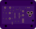
Hello. So I need help modding a project. It's a timer for a solenoid valve used to slowly bubble CO2 into a reactor. Now I've actually put this together already and it works without issue. My problem is that I want to make another however the solenoid I was using is so much easier to find in 24VDC. Now I was just going to get the appropriate power supply and plug it up until it dawned on me that the original design was probably put together with a 12VDC power supply in mind and adding a 24VDC power supply probably won't work............and might be dangerous. The person who originally posted this project has vanished so I figured I'd roll the dice here. I know almost nothing about electronics besides a few basics so any help would be appreciated. Here's the project...
simple_rev0.png

And here is a link to the BOM... https://octopart.com/bom-tool/KsaVM9dL

Again, any help would be greatly appreciated. -A
 

ericgibbs

Joined Jan 29, 2010
21,448
hi am,
Welcome to AAC.
If you use a 24Vdc supply, adding a 7812 voltage regulator for the logic and 555 , would be one option.
Power the 24Vdc solenoid directly from 24Vdc

E
EDIT:
The MOSFET is rated for 30V.
 

Attachments

Last edited:

AnalogKid

Joined Aug 1, 2013
12,143
As above, run everything except the valve and its LED on a small 12 V regulator.

Also, Q1 should be changed to a 60 V part. The part on the schematic is rated for 30 V, too close to 24 V for comfort. For better long-term reliability, the transistor should be rated for at least twice the voltage it will see.

Where are you located, and do you have access to an electronic component distributor (something other than a hobby shop)?

ak
 

iONic

Joined Nov 16, 2007
1,662
Do you know the specs of the solenoid(how much current it draws?) Other than making sure the 7812 voltage regulator can handle the load current, I'd say ericgibbs has a really simple solution.
 

Thread Starter

amnesiac

Joined Feb 11, 2019
5
Wow, you guys are fast. I didn't think anyone would reply to this today. OK so yeah I'm even more confused than I was before I posted lol. Current draw on the solenoid is something tiny, but I cannot find what it is on the datasheet. I should've included this initially, but I also have boards ready to use. When I made the first one I had to purchase the board in 3's so I had 2 left over. If possible I want this solution to fit the board I already have. So I can just swap out the MOSFET for something rated for 30V+ and I'd be good to go??? Did I hear that right??

3d5d7df3698bf8bbf02111bb1e4246bf.png
 

ericgibbs

Joined Jan 29, 2010
21,448
hi am,
The MOSFET in your diagram is rated for a Vd max of 30Vdc, Id max =30A, so 24V solenoid will be OK.
The 555 and its components will will only be ten's of milli-amps, so a 7812 Vreg at 1Amp will be OK.
E
 

Thread Starter

amnesiac

Joined Feb 11, 2019
5
hi am,
The MOSFET in your diagram is rated for a Vd max of 30Vdc, so 24V solenoid will be OK.
The 555 and its components will will only ten's of milli-amps, so a 7812 Vreg at 1Amp will be OK.
E
Really??? So then I don't need to change anything??? That's awesome!!! THANK YOUUUUUUUUUUUUUUUUUUUUUUUUUUUU!!!!!
 

AlbertHall

Joined Jun 4, 2014
12,626
You need to add a 12V regulator to the board. Can you show us the track side of the board. It may be possible to modify the board to take the regulator.
 

Thread Starter

amnesiac

Joined Feb 11, 2019
5

Attachments

AnalogKid

Joined Aug 1, 2013
12,143
If possible I want this solution to fit the board I already have.
Not possible. Your current board will *not* survive on 24 V without a significant modification.
So I can just swap out the MOSFET for something rated for 30V+ and I'd be good to go??? Did I hear that right??
No.
And I need to replace my Q1 with something like this
No.

Q1 in your schematic is the solenoid driver transistor. You need to ADD the 7812 to the circuit. It is a voltage regulator IC, not a simple transistor.

I still strongly recommend changing Q1 to a part rated for at least 50 V. MIL-HDBK-417, Raytheon, Boeing, and ATT agree.

ak
 
Last edited:

Thread Starter

amnesiac

Joined Feb 11, 2019
5
Not possible. Your current board will *not* survive on 24 V.

No.

No.

Q1 in your schematic is the solenoid driver transistor. You need to ADD the 7812 to the circuit. It is a voltage regulator IC, not a simple transistor.

I still strongly recommend changing Q1 to a part rated for at least 50 V. Raytheon, Boeing, and ATT agree.

ak
Thanks for being so clear on this. And thanks everybody else for the help. Think I got what I need now :)
 

wayneh

Joined Sep 9, 2010
18,108
I didn't study your board to see if there is space but it's not mandatory that the regulator has to sit on the existing PCB. It could be off board, for instance screwed to the inside wall of an enclosure and then attached to the PCB with short hookup wires. Mounting that way would actually provide a bit of heat sinking for the regulator.
 
Top