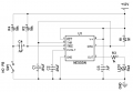
Need Help with 555 microsecond LED Circuit

tracecom

Joined Apr 16, 2010
3,944
All answers refer to the schematic I posted.

By invert it, do you mean that I need to send a constant 5v and then drop the 5v current to trigger it? Or something else?
The circuit already contains a pullup resistor to keep the trigger input at +12V until it is sent a logic low (ground in this case), which is required to cause the 555 to pulse. It will not trigger from a +5 volt pulse.

Also, why 1 pF? Can't I just use my previous capacitor and resistor combination? I already have them laying around and wouldn't have buy them.
The duration of the pulse width is determined by the combination of R1 and C1 according to the following formula: tw = 1.1*R1*C1. Any combination of R1 and C1 which yields 1 microsecond (.000001 second) will theoretically work. I chose 910k and 1 pF, but other combinations will work. 1k and .01μF will not yield 1 microsecond, but rather yield 11 microseconds.

The NE555 is also only rated for 200mA output, how am I supposed to power a 350mA-2000mA LED?
As I previously stated, "you will need to add a circuit to drive the LED's that you plan to use."

In general, it is much easier to divide a design into functional parts, get the first part working correctly, and then add additional functions. One possible sequence is as follows.
Step 1. Get the pulse circuit working at any pulse width.
Step 2. Get the pulse circuit responding to the trigger.
Step 3. Design a circuit to drive the LEDs.
Step 4. Connect the drive circuit to the pulse circuit.
Step 5. Adjust the pulse circuit to 1 μS.
It can be done in another order, but the steps still have to be taken one at a time.
 
Last edited:

tracecom

Joined Apr 16, 2010
3,944
You have the same problem with yours as the OPs. You show a toggle, what do you think will happen if you leave the switch on? Answer, the 555 will be stuck in the on state, this is an illegal condition. A 555 requires a pulse shorter than the duration of the timer on pin 2.
Edited to delete my wrong answer. See post number 30 in this thread.
 
Last edited:

tracecom

Joined Apr 16, 2010
3,944
A timing capacitor as low as 1pF is likely to be too much affected by parasitic capacitances in the IC and the connections to it. This 555 datasheet does not appear to recommend capacitors below 1nF (1000pF) - see pages 7 & 8. http://www.ti.com/lit/ds/symlink/lm555.pdf
Somewhat lower values could be tried (100pF?), but 1pF seems improbably low for this class of circuit.

The timing resistor will need to be altered to give the correct interval - see the nomograph Fig.3 in the datasheet - but note that operation below 10μs does not seem to be specified.
I think you are correct. I didn't look back at the datasheet, but I should have. I took the easy way, left R1 at 910k, and recalculated C1 at 1pF. A better combination would be 910 ohms and .001μF.
 

thatoneguy

Joined Feb 19, 2009
6,359
I'm still thinking on the free running clock idea, all digital solution with the 16Mhz Crystal.

Use the clock + input button to "Gate" a single pulse via buffer w/enable to the BJT that drives another BJT to switch on a 3 or 5W LED. MOSFETs would add a speed penalty that would stretch out the time from the pulse to the time the light is on, and even longer to turn off. Dip Switches could Diode OR the counter outputs together to decide the duration of the flash.
 

Thread Starter

Dleberfinger

Joined Dec 18, 2011
49
I'm still thinking on the free running clock idea, all digital solution with the 16Mhz Crystal.

Use the clock + input button to "Gate" a single pulse via buffer w/enable to the BJT that drives another BJT to switch on a 3 or 5W LED. MOSFETs would add a speed penalty that would stretch out the time from the pulse to the time the light is on, and even longer to turn off. Dip Switches could Diode OR the counter outputs together to decide the duration of the flash.
I have no idea how to do that as well. Feel free to make a circuit and try to explain it. :)
 

Thread Starter

Dleberfinger

Joined Dec 18, 2011
49
You have the same problem with yours as the OPs. You show a toggle, what do you think will happen if you leave the switch on? Answer, the 555 will be stuck in the on state, this is an illegal condition. A 555 requires a pulse shorter than the duration of the timer on pin 2.
I was under the assumption that a monostable 555 circuit was meant to only pulse once despite the length of the input.
 

Wendy

Joined Mar 24, 2008
23,800
Nope, as I keep saying, if (and when) the input pulse is low the output of the 555 is high. This is the reason for a signal conditioner.

The timer only times when the input is high, the input can over ride the timer duration.
 

thatoneguy

Joined Feb 19, 2009
6,359
I have no idea how to do that as well. Feel free to make a circuit and try to explain it. :)
What will the control signal be?

A switch (which could cause multiple flashes due to bounce, unless you get a bounce-free switch for more $$$)?
A 5V signal from the camera shoe?
etc.
 

thatoneguy

Joined Feb 19, 2009
6,359
I have no idea how to do that as well. Feel free to make a circuit and try to explain it. :)
I'm stuck on trying to figure out how to just let ONE pulse through.

The counter is easy enough, a 4060 14 bit Ripple counter w/oscillator The \(2^{4_{th}}\) output (Q3) is Divide by 16 for a 1Mhz pulse train using a 16Mhz Crystal, which leaves very little room for error, as any error in frequency from the crystal would be 16 times less of a timing error.

I'm having a total brainfart on how to let one pulse through then stop again. I'm thinking a buffer with the enable line tied to Q4 then AND with input, but if input lasts longer than 2uS, it would repeat, and that would give the 1uS clock 2uS after requested, and every 2uS after that if the input was held high.

I know I could do it with a $1 microcontroller, which would have an input that goes high then outputs for 1uS, 2uS, 4uS, 8uS, 16uS and 32uS, then wait for the next pulse after 10 milliseconds have passed to avoid switch bounce issues.
 
Last edited:

tracecom

Joined Apr 16, 2010
3,944
Nope, as I keep saying, if (and when) the input pulse is low the output of the 555 is high. This is the reason for a signal conditioner.
OK, I rebuilt my breadboad and Bill is absolutely correct (and my memory was absolutely incorrect.) Here is my corrected schematic with Bill's signal conditioner added. The circuit works correctly, i.e., the button can be held down without affecting the length of the pulse. However, I don't know if switch bounce is a problem.

Note also that I have put in a smaller value for R1 and and a larger value for C1 that still calculate to a 1 μS pulse width, and in fact, the LED does pulse ever so briefly with those components. I don't have a way to measure the duration, but it is so short that it doesn't appear that the LED comes up even close to full brightness.


Attachments

Last edited:

thatoneguy

Joined Feb 19, 2009
6,359
Found this link. LED won't work :(

Specialized Xenon strobes at low power can produce a 800nS duration, though typical Xenon is 10mS at normal powers.

A few people in that discussion tried using LEDs and couldn't get enough light. One even tried a 1μS 100VDC pulse to the LED, and it didn't light up enough, or hurt the LED!

So, it appears the solution is professional strobes (500Watt/seconds+) set at their lowest power to get the shortest duration but brightest flash.

I'd suggest This at 1/128th power Very reliable, and will give you anything from an instant tiny blink, to setting a newspaper on fire when in front of it (seriously). I have too many spendy hobbies.
 

Wendy

Joined Mar 24, 2008
23,800
OK, I rebuilt my breadboad and Bill is absolutely correct (and my memory was absolutely incorrect.) Here is my corrected schematic with Bill's signal conditioner added. The circuit works correctly, i.e., the button can be held down without affecting the length of the pulse. However, I don't know if switch bounce is a problem.

<snip>
This qualifies as a switch debounce circuit. It will ignore other inputs, as long as the low does not exceed the timing duration.

I may be mistaken, but I believe some of the 7400 or CMOS series do not have this problem.
 

Thread Starter

Dleberfinger

Joined Dec 18, 2011
49
Found this link. LED won't work :(

Specialized Xenon strobes at low power can produce a 800nS duration, though typical Xenon is 10mS at normal powers.

A few people in that discussion tried using LEDs and couldn't get enough light. One even tried a 1μS 100VDC pulse to the LED, and it didn't light up enough, or hurt the LED!

So, it appears the solution is professional strobes (500Watt/seconds+) set at their lowest power to get the shortest duration but brightest flash.

I'd suggest This at 1/128th power Very reliable, and will give you anything from an instant tiny blink, to setting a newspaper on fire when in front of it (seriously). I have too many spendy hobbies.
Just FYI. This is still a Xenon flash tube, which, when the tube is so large, it is impossible to get a fast flash out of it. The Xenon gas inside the tube stays excited and emitting light far past whatever time you may put through it. There are special high speed tubes that cost a lot of money and I have even less of an idea how to use them.

If you look at the specs for that studio flash, the light duration is never faster than 1/6000th of a second. My hot shoe mounted flashes give me around 1/50000th of a second exposure when stopped down to their slowest speed.

The LED is my only solution, and I've seen it done with enough light that I can use it for my purposes.
 

Thread Starter

Dleberfinger

Joined Dec 18, 2011
49
Would it be possible to drive a xenon flash tube for around 2 us with an extremely high voltage and low capacitance capacitor? Such as a .1 uF 2000v capacitor?
 

Wendy

Joined Mar 24, 2008
23,800
I had not thought of that, but it sounds doable. Are you familiar with Xenon flash tube transformers? They generate 4KV pulses that ionize the gas inside the tube.

They are very high voltage circuits. The cap is charge to around 130VDC. If you decide to go there double check your work, often.
 

Thread Starter

Dleberfinger

Joined Dec 18, 2011
49
I had not thought of that, but it sounds doable. Are you familiar with Xenon flash tube transformers? They generate 4KV pulses that ionize the gas inside the tube.

They are very high voltage circuits. The cap is charge to around 130VDC. If you decide to go there double check your work, often.
I'm fairly certain they are a little higher than 130VDC. I have yet to find one below 300V. I'm not very familiar with how they work, other than there is a capacitor that ionizes the xenon gases after a trigger current it put into the trigger probe.
 

Wendy

Joined Mar 24, 2008
23,800
I've built a few of these circuits when I was a teen, they are not fixed on the basic charge voltages for the caps. I've seen 130VDC, 180VDC, but not extreme voltages like 300VDC. The trigger pulse is critical though.

Once triggered they will discharge the cap, they are like a switch.

I once worked on a continuous discharge around 300V, but that was to pump a YAG laser.
 

Thread Starter

Dleberfinger

Joined Dec 18, 2011
49
I've built a few of these circuits when I was a teen, they are not fixed on the basic charge voltages for the caps. I've seen 130VDC, 180VDC, but not extreme voltages like 300VDC. The trigger pulse is critical though.

Once triggered they will discharge the cap, they are like a switch.

I once worked on a continuous discharge around 300V, but that was to pump a YAG laser.
I have a number of linear xenon tubes, ranging from 1/4" inch to about 3".

The only way I have to fire them at the moment is a flash unit circuit that I got from an old hotshoe flash.

I need to figure out a circuit to test the tubes with the new capacitor.
 

Wendy

Joined Mar 24, 2008
23,800
Way back when (when I had to walk uphill both ways to go to school) Radio Shack sold a Xenon strobe tube flash trigger transformer. I read an article that mentions all the parts are available from Electronic Goldmine (online retailer).

I also found a schematic I will not refer to at Arron Cakes website. It uses mains as a direct power supply, which is a major infraction here at AAC (we regularly close thread because of it).
 

Thread Starter

Dleberfinger

Joined Dec 18, 2011
49
Way back when (when I had to walk uphill both ways to go to school) Radio Shack sold a Xenon strobe tube flash trigger transformer. I read an article that mentions all the parts are available from Electronic Goldmine (online retailer).

I also found a schematic I will not refer to at Arron Cakes website. It uses mains as a direct power supply, which is a major infraction here at AAC (we regularly close thread because of it).
By mains you mean the AC from the wall? Also, I need it to be DC anyway.
 
Top