
 Facebook
 Google
 GitHub
 Linkedin
(I have been through every thread on the matter and still require amplification, in other words, if someone could break out the Big Purple Crayon to walk the dog here, it would help)
This may look simple to everyone with an EE degree, however...here is a diagram for a simple split coil transformer whose oscillating current is driven (somehow) by two transistors. The inverter portion of the circuit is obviously the portion containing coil P1, coil P2, R (x2), and transistors Q (x2). Easy enough, right? How does this circuit control alternating switching of the transistors that alternates the direction of the current? (To the uneducated, it looks like the transistors would simply fire together, producing a collision)
(Please see attachment - it will not display here for some reason )
)
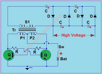
To best illuminate the question, I fully understand the concept of the mechanical switching depicted in the top image here that will produce a square AC-like wave when switched rapidly, but the bottom image's concept of operation eludes me:

This may look simple to everyone with an EE degree, however...here is a diagram for a simple split coil transformer whose oscillating current is driven (somehow) by two transistors. The inverter portion of the circuit is obviously the portion containing coil P1, coil P2, R (x2), and transistors Q (x2). Easy enough, right? How does this circuit control alternating switching of the transistors that alternates the direction of the current? (To the uneducated, it looks like the transistors would simply fire together, producing a collision)
(Please see attachment - it will not display here for some reason
)
To best illuminate the question, I fully understand the concept of the mechanical switching depicted in the top image here that will produce a square AC-like wave when switched rapidly, but the bottom image's concept of operation eludes me:
Attachments
-
 60.2 KB Views: 44
Last edited:






