 Facebook
 Google
 GitHub
 Linkedin
Hi guys got a little project going on with my friend he has a mobility scooter which is 24 volts. Anyway his turn signals and hazard broke it turned out to be his main board and it uses a micro controller to make things work . I got a turn signal wiring harness from another mobility scooter which is also 24v and i need help to wire it up.
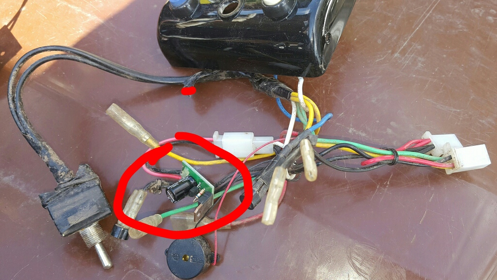
So high lighted in red in the picture it is a 2 pin flasher it got what i believe is 2 transistors
And down the line it goes to a 4 pin bridge rectifier . I will give you any information you need from me best regards james
The switch is on off on and that is used for either left turn or right turn signal
The zoomed in picture is the flasher circuit board


Last edited:


