I have been traveling some, and didn't have a lot of access to the web. I am still following the thread to learn about solar charging. Bernard is amazing with those hand drawn schematics.
I have been traveling some, and didn't have a lot of access to the web. I am still following the thread to learn about solar charging. Bernard is amazing with those hand drawn schematics.
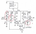
Here is a solar only ckt. I breadboarded a similar one, different LEDs & SP. The red LEDs start at about 5 V, SP in shade, blue joined in at 6 V & all full bright in full sun. As long as SP put out 9 V to 13 V , the LED supply stayed fixed at 9 V. The MOSFET can be almost any N ch available, used 3055V SM because I had some. Used one red LED as V reference @ 1.9 V. Adjustment of R6 was smooth from 8 V to 10 V. Cap could be anything from 1 to 10 μF. Maybe it is a start?
Hi Bernard, I had circled on the attached picture with the below queries;
1) The Infrared LED is wrongly placed in the string?
2) The UV LED is wrongly placed in the string?
3) I do not understand what is the 4 with + - symbol, is it for future battery charging?
All of the high current LED's are in one string, your list shows IR as 60 mA, paralled with 39 Ω to make it 100 mA, note: R2 should be 39 Ω. UV listed as 20 mA, so belongs in 20 mA string. C1, 4 μ F is an electrloytic cap & is polarity sensitive, - to gnd.
Might start with one 150 mA panel & check results, then add second one in parallel to give 300 mA, will prob. operate over greater variations in sun insolation. In future excess power wasted in R5 & FET will be used to charge battery. ' Still have problem with battery, if 9 V simple switching but no recharge; lower V & need boost-- but that is for another day, or help from someone who knows what they are dooing.
Understood on the IR arrangement and the 4u cap. But for UV although it is 20mA but the forward voltage is 3.2V to 3.8V and Red forward voltage is 1.8v to 2.3v. Need to rearrange the LEDs on that string?
Finally the part had arrived. I had completed the circuit at night, so I am using the 9V battery to test run. Everything LEDs lighted up except for the infrared LED. I tried changing other resistor value also does not help to light it up. Any idea what is wrong?
Also can I know what is R1 for and how to calculate it?
Finally the part had arrived. I had completed the circuit at night, so I am using the 9V battery to test run. Everything LEDs lighted up except for the infrared LED. I tried changing other resistor value also does not help to light it up. Any idea what is wrong?
You know that the IR LED is not visible to the human eye, right? If you have a digital camera, look at it through the camera, and if it's lit, you should see it on the camera screen.
Finally the part had arrived. I had completed the circuit at night, so I am using the 9V battery to test run. Everything LEDs lighted up except for the infrared LED. I tried changing other resistor value also does not help to light it up. Any idea what is wrong?
Also can I know what is R1 for and how to calculate it?
You know that the IR LED is not visible to the human eye, right? If you have a digital camera, look at it through the camera, and if it's lit, you should see it on the camera screen.
Yes i know that, I use all my iphone 3GS, 4 and 5 and even ipad 2 to look at it but not lited. I remove my infrared LED and using a LED tester, it shine when I use my camera to view it.
I had constructed my solar cell together with 14 piece of 2V 150mA to output 14V 300mA. Attached it to the circuit and it works fine, nothing seem to be overheated. Even on the shady time, the LEDs are still very bright except for the infrared LED which did not light up. I check the current flow thru R2 39 ohm resistor which is around 70 to 85mA. So I replace R2 with 47 ohm to adjust it closer to 60mA but still did not light up.
Anyway does anyone have any idea what is R1 10 ohm doing in the circuit?
No worry, he told me on 19th Aug, he would not be around for a week.
Anyway I think I can ignore the Infrared LED, just curious why it didnt work in practical. Guess that's why electronic is so challenging.
Also tracecom, is there any other methods which can allow the LED to draw 20mA for optimum brightness but lower the overall power consumption of the circuit. Sorry if I confuse you as I do not really how to phase the meaning I wanted to ask in electronic terms . I read somewhere that making a Pulse Frequency 720Hz or higher to power the LEDs will reduce power consumption yet maximize the grow light effect I wanted to make for indoor plant. Is it possible to alter in this circuit?
Adding PWM would be easy, but also would create lots of uncertainity, might make a good oscillator without carefull selection of timeconstants. I would rather see a completed system tested before adding more complications.
R1 is a current sense, with 100 mA flowing, there will be a 1V drop, compared to a 1V reference, keeps current constant @ 100 mA.
The only reason that I can see for IR not working is that it is reversed. R2 protected IR from distruction by dropping V to 3.9V which is lower than rated reverse V of 5V. There should be about 40 mA thru R2, the remainder of the 100 mA thru IR.
California was nice to visit, ocean quite choppy, but nobody got seasick.
What should I do or check base on the above? As mention I had removed the IR, but still would like to learn how to make it work. Other than that the circuit is almost completed except for battery and charging. Then maybe the PWM you mention to save more power?
Most LEDs , cathode is short lead, flat on case = K, larger element in case = K, or check with hi range on analog VOM, normally black lead = k with conduction; or maybe your LED tester will give polarity. Cathode to R1. Other possible fault is leads are not making contact with socket; might try measuring V across the IR leads while in the ckt.
Most LEDs , cathode is short lead, flat on case = K, larger element in case = K, or check with hi range on analog VOM, normally black lead = k with conduction; or maybe your LED tester will give polarity. Cathode to R1. Other possible fault is leads are not making contact with socket; might try measuring V across the IR leads while in the ckt.
Very sure the polarity is correct and I check the voltage across IR is 1.54v. Anyway I think to reduce the circuit overall power consumption, I had remove the 2 X blue @100mA & IR and replace with a 180ohm resistor & 2 X blue @20mA in that string.
Do I need to remove R1 or change the value? So far without change the value works fine but I don't know what will it affect in a long run.
 Facebook
 Google
 GitHub
 Linkedin