Need help to light up 8 LEDs with different color

Thread Starter

jenovauh

Joined Jul 4, 2013
246
jenovauh,

I am glad you are making progress. Bernard has much more knowledge than I have, and can give better advice on battery chargers.

May I know what is the purpose of your LEDs?

Bernard,

Thanks for your help.

I will be back on more regularly in a few days.
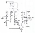
I try to make this circuit for my indoor plant, they does not look healthy without the light they needed.

By the way for the charging for 2 x 3.7V Lithium battery, is it very difficult to achieve? Or is there any other battery should be using instead of Lithium battery?
 
Last edited:

Bernard

Joined Aug 7, 2008
5,784
Untill we can resolve battery and charging, you might want to operate on solar only. I suggest making 2 solar batteries of 8 cells each. Without a battery D1 & D2 are not needed yet. R1 is a ketcholl depending on SB output, current limitation of zener diode & ?? Blue LEDsthe full 100 mA by shunting IR LED with 38 Ωs,. There should be ample current for battery charging when that comes into play. Worth a try??
 

Attachments

Thread Starter

jenovauh

Joined Jul 4, 2013
246
Untill we can resolve battery and charging, you might want to operate on solar only. I suggest making 2 solar batteries of 8 cells each. Without a battery D1 & D2 are not needed yet. R1 is a ketcholl depending on SB output, current limitation of zener diode & ?? Blue LEDsthe full 100 mA by shunting IR LED with 38 Ωs,. There should be ample current for battery charging when that comes into play. Worth a try??
Hi Bernard, the circuit you attached will surely works. I used to connect directly to the solar cell, but sometime when there are no sun mean no light. That is why I want to use batteries plus solar cell charging. :)
 

Bernard

Joined Aug 7, 2008
5,784
After you put new ckt together, take some voltage & current measurements so that we can plan charger. The only battery charger that I have made was for 24 D cell NiCd's back in 1974. Never had a Li battery.
There are several tasks involved with this project:
Boost ckt for battery, at near discharge not enough V for LED's, look at project by TexAvery. post # 41, something similar might work.
Battery charge cutoff & low V disconnect.
Ckt to tell when boost is needed, & kill charging.
Day- night detection, solar panel V drop at night is a good indicator.

Maybe some battery charger people will come to your aid.
 

Thread Starter

jenovauh

Joined Jul 4, 2013
246
After you put new ckt together, take some voltage & current measurements so that we can plan charger. The only battery charger that I have made was for 24 D cell NiCd's back in 1974. Never had a Li battery.
There are several tasks involved with this project:
Boost ckt for battery, at near discharge not enough V for LED's, look at project by TexAvery. post # 41, something similar might work.
Battery charge cutoff & low V disconnect.
Ckt to tell when boost is needed, & kill charging.
Day- night detection, solar panel V drop at night is a good indicator.

Maybe some battery charger people will come to your aid.
Hi Bernard, it is alright I can change the batteries anytime to make things easy. Really does not need to be Lithium batteries if it is difficult to achieve.
 

Thread Starter

jenovauh

Joined Jul 4, 2013
246
Li should be allright. I drew up an outline but I'm out of time untill Monday. I have the solar panel shown, battery is LiFePO4, similar to yours.
Hi Benard, thanks again. I will try to understand the circuit as it looks complicated to me :).

Anyway I wants to know if my application for the LEDs light are complicated or practical for electronics? I personally thought that it should be a simple circuit with 8 LEDs light, auto on/off under environment ambient with recharging.

If you guys know a better or easier way to achieve what I need, I am ready to change as I do not want to make anyone headache who is helping me.
 

Bernard

Joined Aug 7, 2008
5,784
To me , it seems like over complication, maybe just solar, no need for day-night contril, & it's a really dark day when no solar power is produced. Example my panels, rated at 5.5 kW, on average day produce 4.5 kW & cloudy, light rain produce 1.5 kW. Why not try it for awhile?
 

Bernard

Joined Aug 7, 2008
5,784
Sorry about not giving parts lables, but I'm again short of time.
U1, P-chanet FET; U2, U5, U6.U9 & U12, comparators sim. to LM339N. U12 was OP Amp but comp. works fine with no gain change. U4 & U7 are CMOS R-S FF, flip-flops; U8 CMOS 2 input OR gate. U11, Boost needed only needed if battery V is not ligh enough to keep LEDs lit at near discharge V.
 

Bernard

Joined Aug 7, 2008
5,784
I took part of ckt dealing with normal daytime operation & put it on a breadboard. Assume that SP will provide more than the 100 mA needed by the LEDs. A V Rf, voltage reference of 1.2 V is provided by LM 385Z, & is divided rown to .22V by 10k pot. When 100 mA flows thru 2.2 Ω, V drop is .22 V, the crossover point of comparator U 12, causing gate V of U1 to start falling ; enough current now flows into B, battery, to load SP enough to keep 100 mA flowing in LED's & excess I into B, about 50 mA. The next step would provide over V control by shorting U12-2 to ground, cutting off U1. Low B V acts the same way, turning off U1.
After you opperate LEDs on solar only for awhile, we can hopefully see if a boost ckt. is needed, also dependent on minimum operational battery V.
 

Attachments

Thread Starter

jenovauh

Joined Jul 4, 2013
246
I took part of ckt dealing with normal daytime operation & put it on a breadboard. Assume that SP will provide more than the 100 mA needed by the LEDs. A V Rf, voltage reference of 1.2 V is provided by LM 385Z, & is divided rown to .22V by 10k pot. When 100 mA flows thru 2.2 Ω, V drop is .22 V, the crossover point of comparator U 12, causing gate V of U1 to start falling ; enough current now flows into B, battery, to load SP enough to keep 100 mA flowing in LED's & excess I into B, about 50 mA. The next step would provide over V control by shorting U12-2 to ground, cutting off U1. Low B V acts the same way, turning off U1.
After you opperate LEDs on solar only for awhile, we can hopefully see if a boost ckt. is needed, also dependent on minimum operational battery V.
Okay I will try to get the part and try the currents. I do not have a lot of part you had in the schematic. By the way, is FDS9435 is a SMD part? I could not find DIP part for that.
 
Last edited:

Bernard

Joined Aug 7, 2008
5,784
The last ckt. was not ment to be constructed, just a breadboard test, which was successfull, although it took about 23 hours to charge the battery. I'm going to try a simpler solar only controller today with a real SP, not a synthisized one.
 

Thread Starter

jenovauh

Joined Jul 4, 2013
246
The last ckt. was not ment to be constructed, just a breadboard test, which was successfull, although it took about 23 hours to charge the battery. I'm going to try a simpler solar only controller today with a real SP, not a synthisized one.
I see. so do you have the exact part list for the previous schematic? Or do you want me to constructed it or wait for your next test? Anyway I will also need to test on breadboard before constructing it.
 

Bernard

Joined Aug 7, 2008
5,784
Here is a solar only ckt. I breadboarded a similar one, different LEDs & SP. The red LEDs start at about 5 V, SP in shade, blue joined in at 6 V & all full bright in full sun. As long as SP put out 9 V to 13 V , the LED supply stayed fixed at 9 V. The MOSFET can be almost any N ch available, used 3055V SM because I had some. Used one red LED as V reference @ 1.9 V. Adjustment of R6 was smooth from 8 V to 10 V. Cap could be anything from 1 to 10 μF. Maybe it is a start?
 

Attachments

Thread Starter

jenovauh

Joined Jul 4, 2013
246
Here is a solar only ckt. I breadboarded a similar one, different LEDs & SP. The red LEDs start at about 5 V, SP in shade, blue joined in at 6 V & all full bright in full sun. As long as SP put out 9 V to 13 V , the LED supply stayed fixed at 9 V. The MOSFET can be almost any N ch available, used 3055V SM because I had some. Used one red LED as V reference @ 1.9 V. Adjustment of R6 was smooth from 8 V to 10 V. Cap could be anything from 1 to 10 μF. Maybe it is a start?
Okay sure I can try that first while you work on the SP and Lipo charging. :)
By the way I have some IRLZ44N, can i replace them for 3055V or IRF740?
 
Last edited:
Top