 Facebook
 Google
 GitHub
 Linkedin
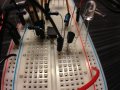
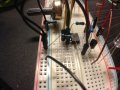
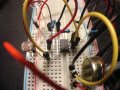
Hi Tracecom, I follow the schematic but I could not clearly see how to attached the LED into the circuit. Never use a BS170 before, can you advise on that? Thanks.Here is a photo of my solderless breadboard. Notice that I put one blue LED on the output of the BS170 MOSFET to test the circuit. And in the photo, you can see that the blue LED is lit because of the flash on the camera, so the response is quite fast.
All black wires are ground, and all red wires are Vcc. All resistors are .25w. I didn't label the components, but you can probably figure out which is which. If you have questions, just ask.
Last edited:


")


