Need help to light up 8 LEDs with different color

Thread Starter

jenovauh

Joined Jul 4, 2013
246
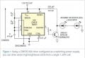
Hi everyone, I am new to electronic and had been searching for a circuit I can use for my project. So far I had see one close to what I need but doesn't work/light up when I mixed with different color LED. And I did not have the correct 555 timer which need CMOS and mine is NE555. So the brightness of the LED is very dim (with same color LEDs) and not to mention to use more LEDs. I had attached a picture of the circuit which I tried to replicate.

I actually wanted to power up 4 Red LEDs, 2 Blue LEDs, 1 Infrared LED and 1 Ultraviolet LED, able to switch on in daytime and shutoff at night. If possible, connect to some 2v 150mA solar cell to recharge the battery. Hope someone can help me with this. Thanks you so much for reading.
 

Attachments

tracecom

Joined Apr 16, 2010
3,944
The reason that the circuit you posted uses a CMOS 555 is because of the low supply voltage. What is the power source you plan to use? State the voltage and current of your power source, and that will be a starting point for the design.
 

Thread Starter

jenovauh

Joined Jul 4, 2013
246
The reason that the circuit you posted uses a CMOS 555 is because of the low supply voltage. What is the power source you plan to use? State the voltage and current of your power source, and that will be a starting point for the design.

Hi Tracecom, I wanted to use 2 X 1.2V rechargeable 1800mAh Ni-MH AAA battery. Actually I am not sure if it is possible, I am open to all changes to make what I need works.

I do not know if the information below is important
Blue LED If=100mA Forward Voltage is 3.2V - 3.6V
Red LED If=20mA Forward Voltage is 1.8V - 2.3V
Infrared LED If=60mA Forward Voltage is 1.5V - 1.6V
Ultraviolet LED If=20mA Forward Voltage is 3.2V - 3.8V
 
Last edited:
CMOS (Complementary Metal Oxide Semiconductor) -- runs down to ~3VDC. Valid logic high is > 73% of VCC and logic low < 26% of VCC.

Leds have varying forward voltage drops. Red ~1.8V. Green ~2.1V. Blue ~3V. Throw a capacitor on the output for a bit more punch?

Yeah throw a large electrolytic on the output for a bit more punch.
 
Last edited by a moderator:
Hi Tracecom, I wanted to use 2 X 1.2V rechargeable 1800mAh Ni-MH AAA battery. Actually I am not sure if it is possible, I am open to all changes to make what I need works.

I do not know if the information below is important
Blue LED If=100mA Forward Voltage is 3.2V - 3.6V
Red LED If=20mA Forward Voltage is 1.8V - 2.3V
Infrared LED If=60mA Forward Voltage is 1.5V - 1.6V
Ultraviolet LED If=20mA Forward Voltage is 3.2V - 3.8V
If you drive those leds extremely hard, then their drop will increase. NTC (Negative Temperature Coeffecient) all semiconductor material.

Keep this in mind too.
 

Thread Starter

jenovauh

Joined Jul 4, 2013
246
I see, thanks for the information. Could you help with a design that I can work on or redirect me to a circuit I could use as I have no idea how to come out with one as I am still learning.
 
Last edited:
I see, thanks for the information. Could you help with a design that I can work on or redirect me to a circuit I could use as I have no idea how to come out with one as I am still learning.
You don't know enough to question things and or do your own thing. Read and build things exactly as the instructions tell you. Just build and read. No experiments.
 

Thread Starter

jenovauh

Joined Jul 4, 2013
246
I do not know how to start with to make what I need to work. I repeat again, I am totally a newbie to electronic. Had only experience with some electronic kits and know how to read some of the circuit symbol and term. How to design my own when I only have that much of knowledge? That's why I am seeking help from the expert in this forum.

Below is what I want to achieve if you are not aware of;

I actually wanted to power up 4 Red LEDs, 2 Blue LEDs, 1 Infrared LED and 1 Ultraviolet LED, able to switch on in daytime and shutoff at night. If possible, connect to some 2v 150mA solar cell to recharge the battery.
 

tracecom

Joined Apr 16, 2010
3,944
Are you wanting all the LEDs you listed to be on simultaneously, and continuously during the day and off at night? If so, you will need more voltage and current than two AAA batteries can supply. More information about the purpose of your circuit will help you to get better responses.
 

Bernard

Joined Aug 7, 2008
5,784
Just a few thoughts: If Blue could be dimmed a bit to 60 mA, could put 2 Blue & IR in one string; 1 Red & 1 UV for second string; 3 Red for 3rd string. Suggest Vcc of about 10 V. The drain on 3 parallel strings is about 1 W. If Vcc derived from 2 AA Ni-MH running for 8 hours would try to draw about 5 Ah,; need bigger batteries or more in series.
 

Wendy

Joined Mar 24, 2008
23,415
Actually an electrolytic on the output would do very little good, and some bad. It would effectively reduce the RMS voltage the transistors see, since a portion of the waveform would now reverse bias the transistor.

You really do need 3V for a CMOS 555, because as you reduce the power supply voltage the drive characteristics go way down. At 2V you would be lucky to have enough current to turn the transistor on. It will be incredibly weak.

I have designed something very similar for the AAC book.

CMOS 555 Long Duration LED Flyback Flasher

The more LEDs you drive, the shorter time the batteries will work for the circuit. At 8 LEDs you will need 20 to 28 volts, which from a small voltage can be reasonably hard to generate from a flyback pulse.
 

Wendy

Joined Mar 24, 2008
23,415
To the OP:

If you want to light several LEDs you will need at least 2V or more, I don't know where you got that schematic but it is bogus. 2V is technically the minimum voltage for a CMOS 555, though it may work for a few LEDs when you cheat at 1½V. Eight LEDs? No way.

It would be simpler to build several single transistor joule thieves off a 1½V battery instead of trying to make one massive driver off a underpowered chip.

If you would like help with this project just let me know. I have quite a few 555 articles I have written for this site, enough of which it is kind of an inside joke on AAC about me and 555s.
 
Last edited:
There is no SSR diode in that circuit. What are you talking about? It is a CMOS 555 driving a common emitter transistor, which in turn drives a flyback coil that creates relatively HV pulses that translate into current.
Oh my mistake sorry. There is no tank ckt? I mean you could, you could modify it is what I am saying.
 

Wendy

Joined Mar 24, 2008
23,415
No tank circuit, and it would kill the whole concept. I would recommend you read my article I referred to in post #12, as I include a theory of operation.
 

Thread Starter

jenovauh

Joined Jul 4, 2013
246
Actually an electrolytic on the output would do very little good, and some bad. It would effectively reduce the RMS voltage the transistors see, since a portion of the waveform would now reverse bias the transistor.

You really do need 3V for a CMOS 555, because as you reduce the power supply voltage the drive characteristics go way down. At 2V you would be lucky to have enough current to turn the transistor on. It will be incredibly weak.

I have designed something very similar for the AAC book.

CMOS 555 Long Duration LED Flyback Flasher

The more LEDs you drive, the shorter time the batteries will work for the circuit. At 8 LEDs you will need 20 to 28 volts, which from a small voltage can be reasonably hard to generate from a flyback pulse.
Hi Bill, I got the circuit from this forum. I attached the pdf file and the title is "555 timer drives multiple LEDs from one
NiMH cell". Anyway beside this circuit, can I know what is the correct method or schematic in this forum which I can follow to achieve what I need?

Sorry if I made you guys confused as I do not really know the terms well. :)

Below is what I hope to achieve:
- A circuit to power 4 different color LEDs.
- Able recharge using 2v 150mA solar cell (I have 6 pieces)
- the LEDs will turn on in daytime and off at night time.
 

Attachments

tracecom

Joined Apr 16, 2010
3,944
I'll try one more time to understand what your constraints are.

If you are limited to six solar cells that produce a maximum of 2V at 150mA each, and you want to recharge the batteries using only those cells, then you must not draw more power from the batteries than the cells can produce. In the best case (bright sun, best angle), those six cells will produce 1.8 watts. Realistically, they probably will not average more than one watt output during daylight hours. So, you have only one watt that you can draw from your batteries if you expect the solar cells to recharge the batteries.

Next, if you are limited to two 1.2V batteries, then you can connect them either in parallel, in which case you have 1.2V, or in series, in which case you have 2.4V. Thus, the only LEDs which you could light would be those with less than 2.4V drop, i.e., the red (1.8 - 2.3V) and the IR (1.5 - 1.5V), and that would be with the batteries in series. Without some voltage boost circuit, it would be impossible to light the blue or the UV.

So, you don't have enough voltage from the batteries to light the LEDs, and you don't have enough current from the solar cells to recharge the batteries. Therefore, you must have more batteries and more solar cells in order to light all the LEDs you have listed to full brightness.

What options will you consider? More batteries, more solar cells, or fewer LEDs?
 
Top