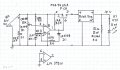
I thought it be usefull to check battery cutoff V & battery reconnect V, maybe reconnect V is a bit too high, something like 12.5 V rather than 13 V+- where I think it is now. Might use pot for R30 then replace with fixed value for desired re-connect V.
Today is overcast so tried simulating " Sun Stretcher" which gleans some power from SP when there is insufficient sun for normal operation, from 0 power to 25% to 50% of time with power.
jenovauh, you may want to add this ckt. after your LED ckt. is up and running, which should not be long as I believe tracecom's ckt is ready.
The Solar Gleaner ckt. is kind of a follow on to the " Mini- Maximiser " & " Solar- Bot." which extracts a little more power when there is insufficient solar power to directly operate a load. The OC, open circuit V of a solar panel, SP, stays relativley high for any sun condition, so a capacitor can be charged from SP, slowley with slight sun, fast with full sun. A SP parallel to sun, low output, 120 Ω load, only reached 3V, load requires 10V. With Gleaner, full 10V to load for 1 sec. 4 sec to recharge and repeat the cycle; so about 20% of power saved.
Transferr V was set at 18V high, 12.5V low, SP OC = 21 V.
I thought it be usefull to check battery cutoff V & battery reconnect V, maybe reconnect V is a bit too high, something like 12.5 V rather than 13 V+- where I think it is now. Might use pot for R30 then replace with fixed value for desired re-connect V.
I still am not sure exactly what I am looking for, but here's what I did.
Disconnected B1 completely, and connected R100-2 to the B1 buss (R18-2 for example.)
Attached one DMM to R100-2 and another DMM to D5-2.
Set D100-2 to minimum and began slowing increasing SP output.
D100-2 = 1.21V, D5-2 = .044V, DA, DC, DD, DE out
D100-2 = 1.65V, D5-2 = 1.586V, DA, DC, DD, DE out
D100-2 = 2.87V, D5-2 = 2.77V, DA, DC, DD, DE out
At this point further rotation of pot on the BB representing the solar panel seems to have very little effect on the voltage at D100-2. After several complete turns, D100-2 = 3.09V, and then suddenly, D100-2 jumps.
D100-2 = 11.88V, D5-2 = .166V, DA, DD, DE lit.
Began decreasing voltage at D100-2.
D100-2 = 11.24V, D5-2 = 10.73V, DA and DE lit, DC and DD out.
As voltage at D100-2 decreases, D5-2 decreases and trails by about .4V
At D100-2 = about 8V, it suddenly drops to 2.96V and D5-2 drops to 2.90V, all LEDs out.
I have no idea if I have done what you wanted. I am sorry, but you will have to give me step by step instructions to get better results.
tracecom, you were close; what we were trtying to do was to set B1 dropout V & reconnect V. Using BB100, "SP", as a variable V source, conected to nothing else except B1 buss, to represent B1. Starting with BB100 at 12.3V, normal B1 operating V, LED-DD, green should be on. Slowley decrease V untill green goes off & note V. Readjust R 28 if necessary to set dropout V to abuot 11.8 to 12 V. Drop V to below 11V, DD off, & increase V untill DD comes on, note V. Should come on at around 12.5 V. If not close, either increase R 30 , or replace with 500k-1 M pot & set to 12.5 V, then replace with closest std value.
Can remove R101, used to check dropoutV. Reconnect BB 100. Should be good to go.
R28 seems to have little to no effect. With R28 fully CW, DD goes off at 11.52V; with R28 fully CCW, DD goes off at 11.47V. That is with R19-2 connected to B1 buss; otherwise the voltage divider has no positive reference, I think. (That is with R100 out of the circuit.)
If I put R100 back in the circuit and reconnect R19-2 to R100-2, and take power for the B1 buss from R100-2, the off point for DD shifts to 11.60V regardless of the setting of R28.
Confusion prevails. We have set B1 cutoff before, #326, pg 33, now we're just using a different variable V supply to do the same thing; wonder what has changed? R 19 has nothing to do with B1 cutoff. With R 28, connected to U4.2, full high, DD should switch off at about 6.9V from simulated B1 V; with R 28-2 at 2.8K from gnd. DD should switch off at 12V. ?, what is V at U4.2-5 when DD on? [ my est. 2.3V ].
I retraced all the connections on the breadboard, and am now getting a response from R28. With R28 max CCW, DD goes out at about 7V. With R28 at midpoint, DD goes out at 14.7V. With R28 at about 10 o'clock, DD goes out at 9.4V. At 11 o'clock, DD goes out at 10.8V. At 11:30, DD goes out at 11.3V. The best I have done is get DD to go out at 11.9V; it's touchy.
I really appreciate that both Benard and you the experts are helping me on that and had spent so much time on this project. Still need Benard's confirmation and your correction schematics and I think a lot of notes on the adjustment on the circuit to set for live testing.
In the process of rechecking things, I replaced R20. So, today, I tried to recalibrate it (with the power connections unchanged from post 555.) DA stays lit all the time; it dims and brightens as I change the SP voltage, but it never goes out. Should we try to resolve that issue now?
LED-DA dim, sounds like pos. feed back injured or missing. What are V readings of U2.1 & U2.2 ? Start with " SP " around 6 V.
Expected Vs, at pin #s
1... less than 1V
2... 6V
3... 2.5 V
5... 8 V +_
6... same as # 1
7... same as # 2

 Facebook
 Google
 GitHub
 Linkedin